After designing several amplifiers with pentode and beam
tetrode output tubes, and trying multiple options in the Universal and TTA
amplifiers, the time has come for a “exclusive tube type” project. This
amplifier was designed for the 813 beam tetrode tube, and due to size, voltage,
heater voltage, and socket constraints, it is not possible to make it more
universal than it already is. GK71 output tubes could be used instead of 813,
but it would imply both different socket wiring and cap, and different heater voltage.
This project is by all means a “flagship”, in terms of
output power, complexity, and costs involved. While I have tried to make it as
easily reproducible and simple as possible, the voltages are nevertheless
higher than in most common DIY designs, and the output power requires very
serious output transformers. In order to make the amplifier as smooth as
possible in operation, several additional features are introduced – thus in the
end anyone can operate it without particular technical awareness: just turn it
on, and enjoy.
The complexity and costs involved in this project imply that
without the help of several DIY enthusiasts who post at the Audio-Talk forum,
in particular Paul Barker, and the help of Per Lundahl of Lundahl Transformers,
I would not be able to present it. Thus I would like to express my gratitude to
those generous people before exposing the basics of the project.
Design Goals
The first and foremost design goal with this amplifier is
achieving high output power – 30W and more, while using only one output tube
per channel (i.e. pure SE operation). The 813, being a beam tetrode tube, lends
itself very conveniently for that task, particularly having in mind that beam
tetrodes and pentodes are more efficient than triodes.

Most high power SE amplifiers are built with transmitting triodes, like the 211, 845, or GM70. Leaving aside the question whether all these amps really achieve above 30W power ratings, truth is that all are operated at very high voltages, the B+ being 1kV and above. All voltages involved in tube amplifiers are dangerous, but it seems that everything above 500V requires extra care both in components choice, and how the amplifier is approached and measured. At high voltages arcs jump easily, and people can get electrocuted. That said, my idea was to keep the amplifier operating at voltages as low as possible, while achieving the 30W and more output power set as a goal. Most common digital multi-meters can measure DC up to 1kV, thus I assume that keeping the power supply around 800V is reasonable enough choice.
High power SE amplifiers with transmitting tubes operated at
high voltages imply another difficulty – the fact that the driver tubes are
usually operated at much lower voltages. While this can be easily solved with
an additional power supply, my design goal is to keep it reasonable and simple
– one power supply should be enough for all stages of the amplifier.

Design Choices
Keeping the B+ around 800V greatly simplifies the
requirements for the capacitors – I have chosen to use motor run “cans” rated
600V AC, which should be safe for at least 1kV (and probably more). Besides the
fact that those caps impart a particular sonic signature to the amplifier, used
in this application they can be expected to last very long – the DIY-er will
probably never have to change them. Another option is serial connected caps,
where caps rated 500V DC WKG in series would be more than adequate – and due to
the nature of the tubes used, and design choices made, even 450V DC WKG caps in
series would probably be safe enough. Of course, the standard 400V caps could
be used in a series of 3, for a very safe total rating of 1200V. The capacities
required are relatively low, thus keeping the power supply as cheap and
feasible as possible.

Putting capacitors in series decreases the total capacity, but by adopting a power supply with 2 chokes ripple is easily kept at bay. The example power supply illustrates the ripple at the load being just about 5mV (much less than most SE amplifiers), while ripple at the first cap is less than 150V – easy task for any motor-run cap (which is why they last so long in tube amps, and should be applied to the input cap position). With a hybrid bridge, output voltage will be higher for the difference in voltage drop between a 5U4 and the solid state diode used for the lower part of the hybrid bridge. The two chokes used, LL1638 – have a DC resistance of just 36 ohms, which helps improving the performance of the power supply: if different chokes with higher DCR were to be used, the additional voltage drop across the chokes should be accounted for.

The 813 beam tetrode has rather high CCS (Continuous
Commercial Service) ratings, with 2250V maximum anode voltage, 1100V maximum
screen grid voltage, 180mA maximum anode current, 100W maximum anode
dissipation and 22W maximum screen grid dissipation – all intended for class
AB1 operation, and even higher for ICAS ratings… at about 750V across the tube
and slightly above 100mA cathode (total) current, this tube is literally
“ticking”. Ug2 is set just below Ua, thus no single parameter is at more than
70% of the CCS rating, which makes this a very safe operating point, and
probably should allow the output tube the longest possible lifetime.
Screen grid voltage was chosen to be just below the anode
potential. This choice is dictated by the peculiar curves of the 813. The
datasheet shows a slight kink in the lower part of the curves (well, they are
actually more like straight lines), which is the least pronounced at low screen
grid voltages, while it increases with the increase in screen grid voltage.
Thus we might imagine that 400V Ug2 would be a good compromise – but
unfortunately such choice would limit the power output to maybe 15W, which is
definitely not worth pursuing in a project of this magnitude. While at 700V Ug2
the kink is more pronounced, the spacing of the curves allows for approximately
35W power output at several load resistance settings.

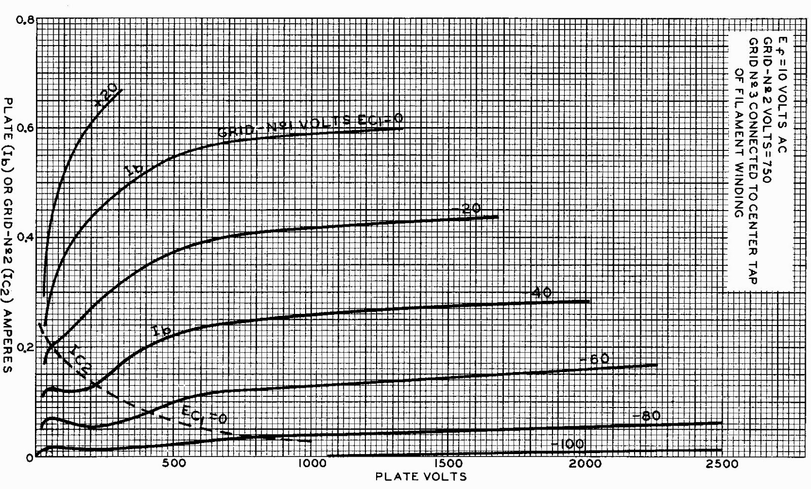
The curves show that 35-36W output can be achieved at similar operating points with both 10k and 5k load resistance. After trying (approximately) 5k, 7k, and 10k load resistance, I have chosen 5k as the load resistance for this amplifier, on the basis of “best sound”. The increase in load resistance does not yield appreciable improvement in performance – actually, both output power/distortion ratio and sound presentation are favorable with an approximately 5k load.
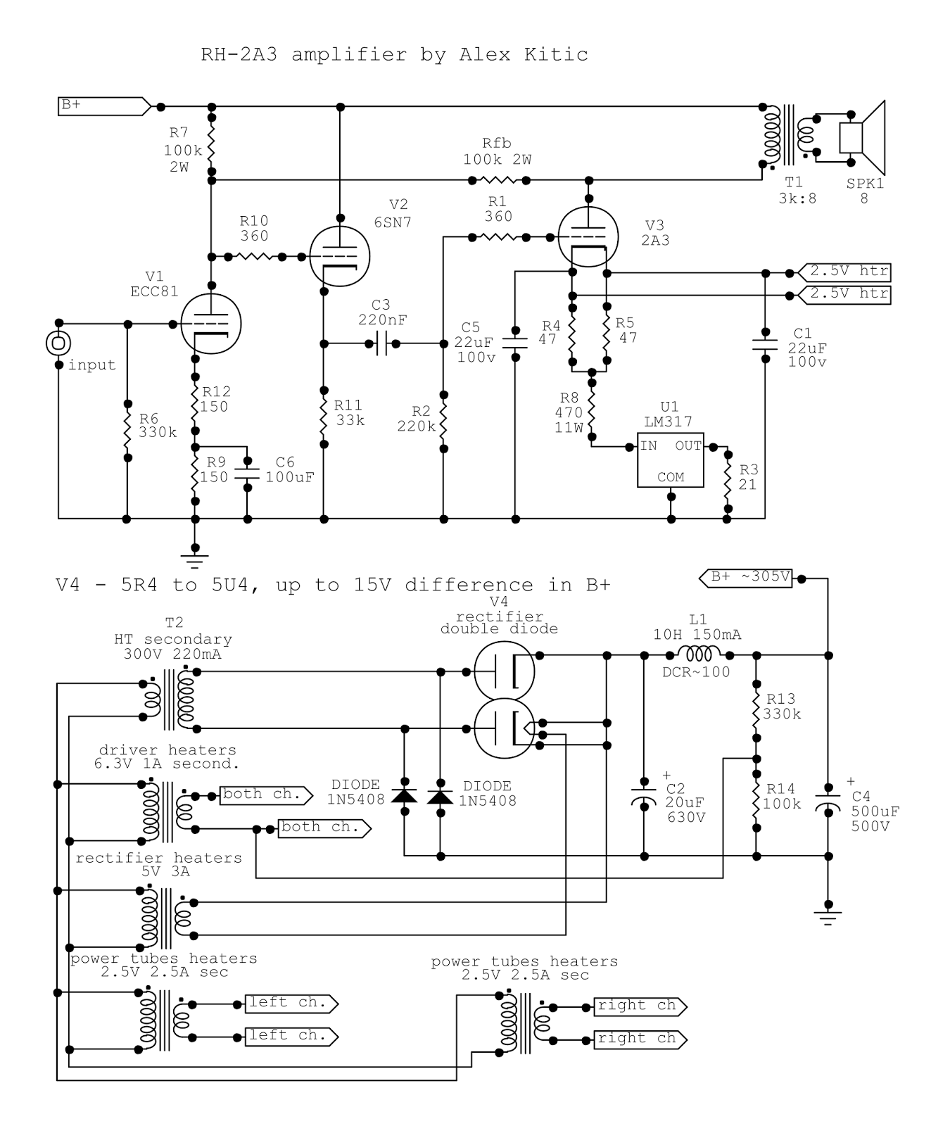
Voltage Regulation Tubes and Driver Section
The driver section is very similar to what already applied
to 2nd generation RH amps – RH300B and the RH2A3 family of
amplifiers (RH-TTA). The ECC81 acts as driver tube, while the cathode follower
tube makes life easier for the driver providing high input impedance, while at
the same time it drives the output tube with low output impedance. Although the
amplifier operates in A1 class (driving the output tube in voltage only), low
output impedance is beneficial with most direct heated tubes due to the gradual
increase in control grid current with the increase of driving signal values.
Besides that, the 813 requires a relatively low valued grid bleeder resistor –
another good reason to apply a cathode follower to driving this tube.
Just like in the other amplifiers mentioned that share the
driver topology – the cathode follower tube could be almost any tube that can
meet the current draw, voltage across tube, and anode dissipation requirements.
The cathode follower tube is direct coupled to the driver tube, thus it is the
driver tube that sets the operating point for the cathode follower tube – the
current draw and voltage across the tube will be almost identical for any
suitable tube used. In this amplifier I have chosen to use the 6SN7, but the
same task could be performed by ECC82 or ECC81 family members – or other
similar tubes like the 6J5, 6N7… For this driver topology it is important to
correctly set the potential of the heaters circuit by connecting the heaters to
a voltage divider like shown in the schematics. The driver tube will have the
cathode at a very low potential, while the cathode of the cathode follower tube
is going to see a relatively high potential, dictated by the voltage at the
anode of the driver – depending on the particular tube used and a few other
details, this will range between 100V and 160V DC – while the maximum allowed
cathode-heater potential difference is 100V DC.

The purpose of the voltage regulator tubes in the circuit is not strictly shunt regulation of the voltage feeding the driver and cathode follower tubes. Actually, regulating this voltage is not particularly necessary in a class A circuit where there is little variation in current draw between minimum and maximum output power. Thus the purpose of these tubes is to facilitate smooth operation and to present a fail-safe feature.
If a directly heated rectifier tube is used, at power up the
B+ will rise quite fast to its maximum level. Since the output tubes are
directly heated and compelled to draw a set current (CCS circuit below the
cathode), they will start drawing current immediately, and B+ will not rise
above normal operating levels. This means that until the driver tube starts
drawing current, the anode will be at a very high potential, and will set the
grid of the cathode follower tube very positive as well. As the cathode
follower tube gradually heats and starts drawing current, the cathode will be
at a very high potential and arcing may occur between the elements inside the
tube.
While there are several other mechanisms that could avoid
this condition (pre-heating the driver tubes, placing a diode between the anode
of the driver and the cathode of the cathode follower – allowing the current to
flow across the anode and cathode resistors in series until the cathode
follower tube heats up and starts drawing current, placing the cathode at a
higher potential than the anode of the driver tube, which in turn makes the
diode “disappear” from the circuitry), the solution with the voltage regulator
string is in my opinion more elegant and predictable, and it offers a fail-safe
function as well.
With the rapid rise of the B+ at power-up, the voltage
regulator tubes light and start drawing current, thereby the driver and cathode
follower tubes are immediately transferred from an 800V environment into the
400V environment for which the circuit was designed. As the tubes heat and
start drawing current, the voltage regulator tubes will draw less and less
current until the desired equilibrium point is achieved. Using 0A2 and 0B2 VR
tubes in various combinations allows a fine tuning of this operating
environment, between 324V (3x0B2) and 450V (3x0A2). In this manner, the tubes
in the driver circuitry are not stressed at power-up, and in operation “enjoy”
some voltage regulation.
The fail-safe function of the VR tubes becomes apparent in case
one or both output tubes do not start (for instance, heater problems) drawing
current. The VR tubes will draw at least 30mA current (actually, in such extreme
conditions they may draw more current, up to probably 60mA, which should not prove
damaging for a short period of time) providing some current draw to the power
supply, keeping the voltage from exceeding a given maximum (in this case, it is
almost impossible for the power supply as designed to exceed 1000V DC, thus the
recommendation for 1000V DC caps rating, i.e. 500V in series: in practice, the
VR tubes would draw up to 60mA and the B+ would not exceed 950V). It goes
without saying that the VR tubes would ignite – being cold cathode tubes, they
do not need anything else besides a minimum voltage potential to start
(provided they are in good operating condition, and these tubes last quite a
long time).
Heating the Output Tubes
The 813 has rather high power requirements – 10V at 5A –
which is basically 50W. Compare it to the 5V 1.2A or 6W required to heat a 300B,
and most problems become apparent.
Let’s start with what I see as the most important problem
when heating direct heated tubes in SE amps – hum. With 50Hz (60Hz) AC, if a hummer
(humdinger) pot or similar arrangement is applied to cancel the basic harmonic,
we are nevertheless left with the residual 2nd (and some higher)
harmonics, i.e. 100Hz (120Hz) hum. The level of hum that can be heard depends
mostly on heater voltage (increases for the square value of the heater voltage,
i.e. it is much higher for 6.3V tubes like the 6B4G than for 2.5V tubes like
the 2A3), and the gain of the tube. Since the gain of the tube in RH amps is
decreased by the feedback loop between output tube and driver tube, we can
enjoy the luxury of AC heaters even with a 300B, probably even on high
efficiency speakers. But hum gradually increases with the increase in heater
voltage and tube gain, and with a 2E22 it becomes difficult to ignore it
completely, at least in the vicinity of the speakers. The 813 requires 10V and
has rather high gain, thus 100Hz hum is virtually impossible to avoid, even in
an RH type amp, and with relatively inefficient speakers: while it may not be
disturbing at the listening position, the presence of hum probably influences
the sound adversely when it comes to fine details in the music.
One obvious solution is DC heating, which should be hum
free. I personally dislike the effect DC heating has on the sound, a specific
type of detail muffling and bass tone exaggeration, and am aware of the other
problems inherent with DC heating, like the difference in heater potential from
one end of the heater to the other, or the need to switch current direction
(polarity) at least from time to time in order to keep the filaments in best
operating condition. Of course, the diatribe between AC or DC for the heaters
of directly heated tubes seems to be never ending – both sides can rely on some
advantages, and since DC is by far more complicated, the supporters of the
latter may be inclined to last longer in this dispute, either due to stakes
held (for instance, offering solutions for sale), or due to investments performed
(buyers of such solutions). But at the cost of being accused of engineering (as
opposed to audiophile) mentality, I would like to avoid the AC vs. DC sound
issue, and stick to what matters: feasibility.
5A of current draw means that at least 9A will be drawn if
rectification is applied. Adding some voltage losses in the process, we are
safe at estimating that at least 100W of power is required for each heater –
which is literally the double of what we should need with AC. Just rectifying
with brute force, like high valued caps, does not present the best solution,
neither as current inrush nor as final result (ripple). Thus some form of
regulation is needed to filter out the ripple without investing in heater
chokes and/or high valued caps. The most basic form would be voltage
regulation, which is as well more energy efficient than current regulation
(lower voltage drop). If we assume using very low drop Schottky rectifier
diodes, and very low drop regulators capable of 5A, like the LM1084, we might
be able to do it with the least energy loss. Still, at 1.5V drop and 5A current
draw, we are facing at least 7.5W of heat for each regulator, which in turn
requires using a hefty heat-sink, or a heat-sink with fan (a good heat-sink for
older Athlon processors will make short work of the heat dissipation).

In the end, we get very low (but still audible, at least I can always hear traces of it) hum or buzz (I like to call it solid-state regulator buzz), and DC on the heaters (which I consider sub-optimal in operational terms, regardless of the sound quality discourse). A lot of energy lost in heating, a lot of complication and effort – and that is why I mention the residual hum or buzz: after going at that long a distance, I expect to get “no hum whatsoever”. Of course, even more elaborate alternatives are possible (several high-quality DC heater solutions are known, advocated, and discussed all over various forums – which pre-made solutions I have not tried due to obvious reasons), and you can always choose the car battery way… but even the car battery adds something audible, some (incredible but true) hum or buzz persists even with battery operated filaments (chemical buzz?).
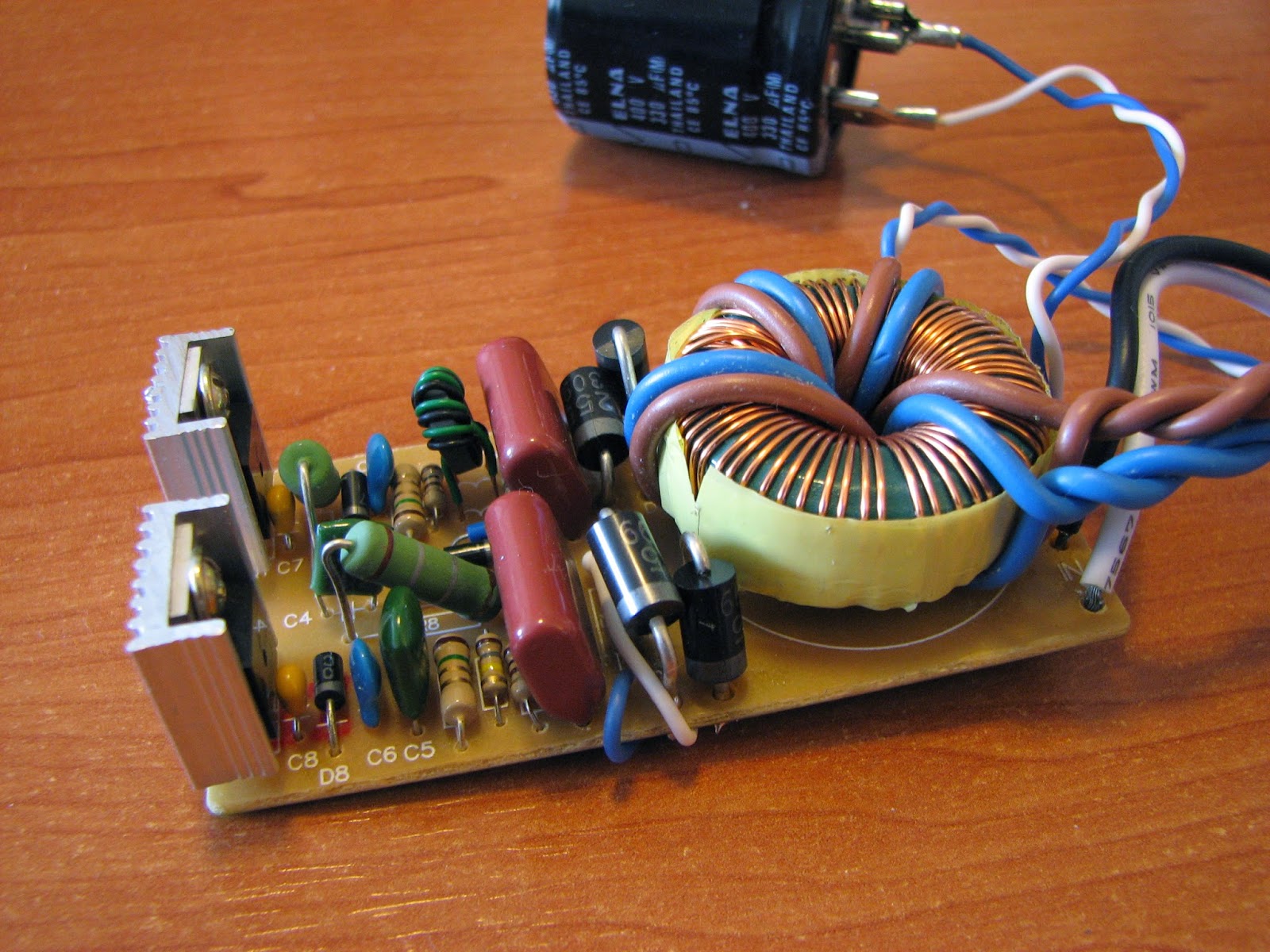
Another solution is high-frequency AC, better known as
“electronic transformer for halogen bulbs”. You can use adequately sized
(minimum-maximum power) electronic transformers straight out of the box, and
drop the voltage with resistors (0.15 ohm per heater leg will do the trick),
but this solution is actually almost identical to what we started with in the
first place – mains AC. The output of the electronic transformer is high
frequency AC (usually between 30 and 60 kHz), but it is “modulated” in 100Hz
format. Once your humdinger circuitry cancels the basic harmonic, you are left
with 200Hz hum, which is slightly less audible than the standard 100Hz, but to
my ears it is also more annoying (it actually resembles the electronic buzz).
In order to be used for this application, the electronic transformer needs to
be modified.

There are two basic modifications to be performed: filtering the initial 100Hz ripple, and setting the correct output voltage. It is rather easy to filter the initial ripple by placing a 270 to 330uF/400V cap (for European 230-240V AC mains) between the positive and negative pole of the bridge that rectifies the mains voltage at the input of the electronic transformer circuitry – but this will in turn cause the output voltage to rise. The rise of the RMS output voltage is proportional to the increase in DC voltage after the bridge (due to the decrease in 100Hz ripple, the average and RMS voltage will be much higher), and with the cap values mentioned is approximately 1.49x the original RMS voltage of the unit. While this excess voltage can be burnt with resistors, due to the high current draw this discourse borders with impractical: we are talking about some 35.5W dissipated in resistors, per heater (per tube). A modification of the output transformer (ferrite core, usually toroid) is necessary, lowering the number of turns in the secondary winding. This is rather easy to do with most electronic transformers.
What is not so easy is getting measurements. In order to
measure HF AC, you will need a True RMS DMM capable of measuring at least 50kHz
– or a scope. The output of the electronic transformer is not a sine wave, but
a square wave, and since this square wave is not perfect, the RMS value is
lower than that of a perfect square wave (which would be equal to the peak to
peak value). Thus either you have an adequate True RMS DMM, or a scope – or you
do a lot of estimation and calculus in order to get the correct value at the
output.

Due to the complexity of the measurement and calculation, this rather easy procedure requires a lot of additional explanation. Since I am quite taken by the results achievable with HF AC for heating direct heated tubes, I intend to post about it in the future with more details. For those willing to try it, and not particularly afraid of learning by trial and error, the whole procedure consists in adding a cap, and unwinding some turns from the secondary of the ferrite core output transformer. The reward for using HF AC will be hum-free sound (less hum than with DC) with all the dynamic qualities of AC on the heaters. The best of both worlds: This might sound like repetition of what I already stated about other solutions in tube audio, but that exemplifies very well what I am after – finding better ways to use what is literally in front of our eyes, but remains unseen or misunderstood.
The Output Transformers
As already explained, I have chosen approximately 5k as the
optimum load for this amplifier based on a combination of sound and
performance. While 10k could offer approximately the same output power with
slightly different parameters, 5k sounds better – more natural and true to
life.
The problem with output transformers for an SE amplifier
this powerful is just that – output power. While most SE transformers might be
safe at the voltages involved in this project (the B+ is well below 1kV, and
even paper insulation should be safe up to 1.5kV if properly applied), and the
total DC current in the primary is not that high as to present a particular
problem in terms of size – most transformers on the market just cannot provide
adequate performance in terms of bandwidth at high output power. The main or
most evident difference between an SE amplifier with 300B tubes, and an
amplifier with 813s is output power – we are talking about maybe 10W against
35W. Even if safe, an output transformer for the usual SE amps will not be able
to perform correctly at high power levels. This fact, and the availability of 813 tubes, has been keeping me from
developing the project for quite some time.

The first pair of output transformers used in this project, courtesy of Paul Barker, are huge and potted units, designed for use with 845 and similar tubes – weighing over 7kg each! I have used these transformers in the initial phase of the project, and they are definitely up to the task – lots of bass and no constraints on output power. Due to multiple taps for the primary (5k, 7k) and the secondary (4, 8, and 16 ohms) – those transformers are easy to use as 5k, 7k, 10k – and even 2.5k and 3.5k if needed.
The second pair of output transformers used in this project
come from Sweden, courtesy of Per Lundahl. While looking like the usual Lundahl transformers – C core, dual bobbin – they are actually twice the size and
weight of the LL1623 I have used in the RH2A3/RH-TTA project. Those
transformers - LL1688 are intended for 845 and similar transmitting triodes, and can
easily be set for 5.5k, 9.5k, or 19k primary – with 4, 8, and 16 ohm speaker
options. Since this time I was after just one setting, there is no wiring
harness or switches – just 5.5k primary into 8 ohms.

While the huge potted transformers performed very well indeed, with great bass extention and lots of volume – I was surprised how much of a difference could a different type of transformer make in the same circuit, and even one which due to feedback mechanisms has lower output impedance and is therefore less demanding than no-feedback types. The improvement in mids and highs, the general liquidity of the sound, and sound-staging was something I did expect – but the LL1688 is better even in the definition and perceived depth of the bass notes. Overall, a clear winner.

Spice Models and Performance


I must admit having started this project without a proper model for the 813 output tubes. After all, some basic driver details are already known, and all I need are the curves – to draw some loadlines. Well, it seems that this is the sub-optimal way of designing amplifiers. Having a loadline is not enough, since the operation of the amplifier is represented by the interaction of the output tubes and the driver section – besides graphic representations of output power and distortion, and the eventual feedback applied, the distortion cancellation effect is very difficult to estimate…

While my 813 model is far from perfect, it is better than most models that can be found for pentodes and tetrodes. The difficulty is getting the “kink” in the lower part of the curves. As for the driver and cathode follower tubes, I have improved all the spice models for triodes that I am currently using to Koren 8 parameter models. Curves from the ECC81 datasheet are shown superimposed with curves obtained from the respective spice model. At this point, what the simulation shows is definitely how tubes should behave…

The Sound and General Impressions
I am always reluctant when it comes to discussing the sound
of my designs – I prefer to hear from others how pleased they are with the
various RH amps they have built. While I tend to explain in great detail the
technical solutions, their eventual elegance and feasibility – the perception
of music reproduction is much more subjective.
This amplifier differs from my other designs in complexity
and power. Power was a design goal, while the added complexity was necessary in
order to keep it user and DIY-er friendly as the previous designs. This
basically means that once built and checked, it can be used for hours, day by
day, without thinking about it – or playing a little bit with the combinations
of driver tubes and operating points made possible by the adoption of VR tubes.

But the sound is really worth mentioning. While the general signature is the same as in other RH amps, due to the nature of the feedback and distortion cancellation applied – this amplifier shows some additional characteristics besides what can be ascribed to the intrinsic quality of the output tubes, more as a consequence of the high power available.
Audiophile DIY-ers with high efficiency speakers are
probably fully satisfied with the power a 300B, or even 2A3 amp can offer –
anything between 5 and 10W is probably enough. But with “the usual” lower or
medium efficiency speakers most people own – each and every W counts. What made
me take the good sound of an EL84 in triode mode and achieve it in pentode mode
with at least twice the power (the RH84 that has started it all), finds its
final gratification in this amplifier. We are not talking here about 5W vs. 2W,
or whether a 300B can give you 8W or maybe 13W… this is power above 30W, and it
seems very easy and so logical – once it is done. But the journey that got me there
was a long one.
With more than 30W at disposal, we are talking about “commercial”
power, something easily achievable with PP amps in the world of shops and
magazines. A simple PP amp with EL34 is capable of 30W per channel… but there
is a huge difference in sound. Once power is not the bottleneck in music
reproduction, we can get to enjoy what was offered or hinted by lower powered
amps. A nicely defined bass note becomes not only nicely defined and precise,
but a loud, fast, and almost brutal attack! A well-defined piano note that had
texture or vibrancy now has power and attack; it resonates in air without being
distorted, almost regardless of listening volume. All of it by far exceeds what
can be had from commercial PP amps, and explains why there is so much hype
about the sound of SE amplifiers.

Endowed by the same sonic signature found in other amplifiers of the RH series while apparently being free of limitations due to its high power, this is definitely the “flagship” RH amplifier – with all the inherent characteristics. Some might ask whether it has the finesse of a 2A3, and the question would be a logical and frequently found one – after all, since the “Ongaku” conquered the world of commercial High End by blitz, there have been so many attempts to scale down the concept. But it is not a fair fight: at low listening levels the RH813 is just as nice, liquid, and enjoyable – as the RH2A3, to name one example. But what it can do transcends the “sound finesse” issue: where it can go, the RH2A3 cannot follow. I guess the question is not absolute, and needs to be rephrased – how efficient are your speakers? Because, if you own very efficient speakers, you probably do not need to go the length necessary, both in financial or psychological terms (higher voltages involved, and higher power consumption/heat dissipation – if that is of any concern, not to mention the fact that bigger is usually more expensive), to involve yourself in an affair with such a behemoth amplifier. On the other hand, the only reason why would you content yourself with a lower power amplifier is either not being able to use it (the neighbors might complain), or not being able to overcome the mentioned financial or psychological issues involved.
An Adequate Box and Other Issues
Starting with the size of the output tubes, and the maximum
dissipation (CCS) possible, as well as the heater requirements in terms of
power necessary – it is obvious that an amplifier like this is not easy to accommodate
in a box, or on a shelf.
The design is relatively efficient – as SE amps can be. By
adopting a toroid power transformer a great reduction in size, heat, and
radiated field is achieved. While the toroid transformer could be a 300VA unit
(output tubes heaters not operated by this transformer), it is rather difficult
to wind the 750V secondary on a 300VA core. Therefore a 500VA core is probably
necessary – increasing both cost and size (but slightly) – but as an aside the
power transformer will be colder in operation. As a matter of fact, the one
used in my RH813 does not exceed 50⁰C – even after 6 hours of operation on a
hot summer day.
The power supply chokes have very low DCR, thus they
dissipate very little heat – and the same is true of output transformers. This
would leave us with the system necessary for the heaters, but instead of 100W
per tube – between transformers and heat-sinks for the regulators and
transistors – there is just a rather small box containing the modified
electronic transformer… and this box, besides being small and efficient, does
not exceed 45⁰C after 6 hours of operation on a hot summer day. Ah, the beauty
of power-efficient solutions.
Thus we are left with the various resistors in the tube
circuit, and the tubes themselves, as the most important source of heat. While
some of the ceramic resistors get quite hot in operation (70-80⁰C), they do not
represent an important source of heat, and the same is true of the driver and
voltage regulation tubes; this leaves us with the output tubes. At 75W
dissipation, and 50W for the heater, the 813s get quite hot and radiate a lot
of power: due to the various heat and power optimizations, they are the most
important source of heat in this amplifier.
Putting the amplifier in a standard size and dimension box
is very feasible – but the height of the output tubes, and the heat they
radiate, means that the amplifier is not suitable to be placed on a shelf. The
heat radiated from the output tubes goes a long way towards burning the shelf
above… thus with an amplifier that is radiating mainly from the tubes, and is
not suitable for shelf placement, should probably be built in a tall and narrow
box. The box should be organized in two distinct levels, the bottom level
containing the power transformer and the output transformers, while on top of
this level lie the chokes and caps and other elements of the power supply. At
the highest level, the opening of the box supports the audio circuit itself,
where tubes protrude from a top cover which is supported high enough to enable
air circulation. This is basically what I intend to build as a box for this
amplifier – to be placed on the floor, beside the shelf with other amps and
audio equipment. Although tall and narrow, the box will have a low center of
gravity, keeping it stable.