Showing posts with label 6201. Show all posts

Friday, February 7, 2014

RH2A3 – An Amplifier With a Twist!


During the final development stages of the RH300B amplifier a similar schematics for use with 2A3 tubes has imposed itself as quite feasible and logical. The 2A3 is a DHT tube just like the 300B, of similar general characteristics: mu is around 4 in both cases, while plate resistance is between 700 and 800 ohms. The main difference between these two tubes, heaters voltage aside, is maximum ratings – dissipation and voltage. Thus slight downscaling of operating voltage and current to create operating conditions acceptable for 2A3 tubes has been done before with several popular schematics.

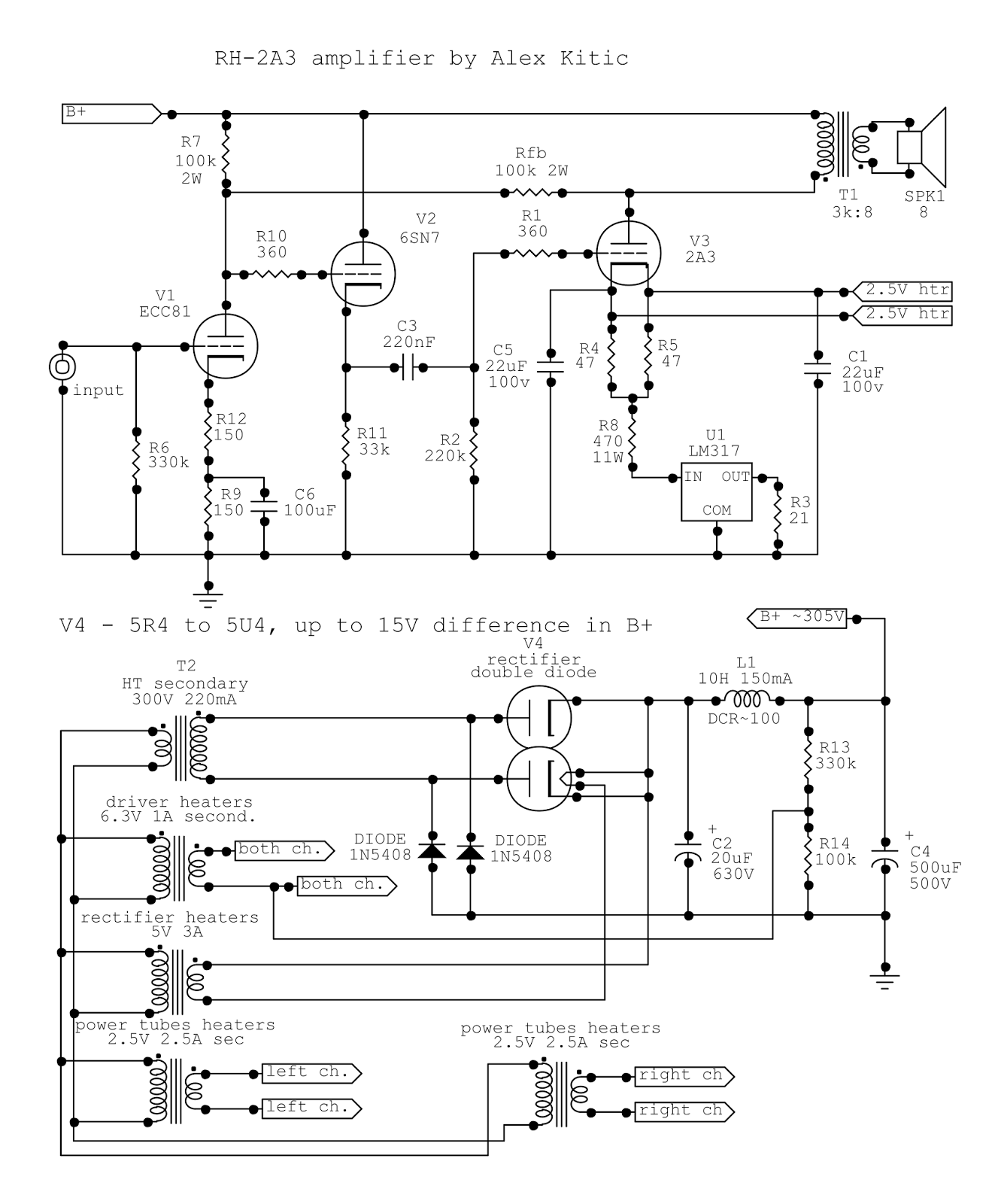
This would be the general RH2A3 schematics – almost a mini-RH300B. With lower B+ and current consumption, cheaper to build due to lower power requirements, different heater voltage for the output tubes, and lower power with the same or similar output transformers. Just as in the case of the RH300B, at 5.1W and 1% distortion, output power exceeds expectations – and will probably be discussed and questioned in the future by all who have not built the amplifier themselves and thus ascertained whether the promise has been fulfilled.


As the schematics is strikingly similar to the RH300B, I shall not repeat all considerations related to the schematics itself – the only appoint that should be made, or rather repeated, is that the operating point of the cathode follower tube is determined by the directly coupled grounded cathode driver tube. Thus it will draw the same current regardless of tube type used – and this time I have chosen to adopt an octal socket, accommodating 6SN7 tubes, but 6SL7, ECC35, and other similar tubes can be used as well – you can go as far as 6BL7, 6BX7… even 6AS7 (or 5998). While it might elude logic to employ 6AS7, 6080, or 5998 (WE421 by TungSol) due to the relatively low current draw, and keeping in mind that these tubes have very high heater current requirements which would have to be taken into account – the sonic results obtainable with these tubes reflects their known sonic characteristics, and are quite interesting in the scope of this amplifier.

The twist


The RH2A3 can be built with regular 2A3 tubes, either NOS or current production: it seems that just like the current production of 300B, modern 2A3 tubes are good sounding, reliable, and meet the “single anode” construction so much sought after by some DIY-ers and audiophiles. And of course, that is the most logical way to go…


But I have built mine with “unusual” 2A3 tubes – on octal base. While the 2A3 tube was manufactured as well with 6.3V heaters and UX4 base (6A3), and further developed into a version with 6.3V heaters and octal base known as 6B4G – I am referring to “special edition” 2A3 tubes, with 2.5V heaters, mounted on octal base. The most notable application of these tubes have been the Audio Innovations First and Second amplifiers, as it seems that 2A3 tubes were custom ordered on octal base due to a lack of UX4 sockets at the time. In my personal opinion, while this is a plausible answer, I guess that commercial concerns were important as well, channeling the supply of spare tubes for the amplifiers.
Anyway, a different base just needs a particular socket, and besides complicating life a little bit trying to source 2A3 tubes on octal bases, this would not be much of a twist. In keeping with the inherent universality of my designs, at this point the 1619 enters the stage. The 1619 is a direct heated beam tetrode tube on octal socket. It has 2.5V heaters just like the 2A3, and is pin-compatible with the octal socket used for octal 2A3 tubes – pins 2 and 7 for the filamentary cathode, 3 for the anode, and 5 for the control grid.


So far so good - but what about the second grid and the beam forming plates? While the 1619 is used by some in triode configuration, with g2 connected to the anode – this application is almost reserved for the old radio collectors market. The 1619 is seen as a cheap replacement for expensive 45 tubes, and relatively elaborate adapters are being made or sold to allow plugging the 1619 in old radio receivers. In the case of the RH2A3/1619 amplifier, the second grid on pin 4 is connected via a zener diode to B+ (56V 5W zener recommended, setting the g2 voltage at approximately 250V), while the beam forming plates (pin 8) are connected to the shield (pin 1) and directly to ground. Furthermore, pin 6 – which is missing on 1619 tubes – is used as the “virtual cathode” point. Pins 4, 6, 8, and 1 are NC on 2A3 octal base tubes, just like they are NC (not connected) on 6B4G tubes (as a matter of fact, the octal base of the 2A3 octal is identical to the 6B4G base). Thus when a 2A3 is plugged into the socket, it is indifferent to the connection of these pins.


How to make it all work?


Both tubes have 2.5V heaters with similar current consumption, and 15W anode dissipation ratings. But the bias voltage of the 2A3, i.e. the potential of the cathode in respect to ground, is much higher than that of the 1619. At the foreseen operating condition of approximately 250V across the tube and (exactly) 60mA of current draw, the bias voltage of the 2A3 exceeds the ratings of the LM317 regulator. While this could be solved by adopting a TL783 regulator which is safe for input voltages of up to 125V (the main and probably only relevant difference between these two regulators is the adoption of a DMOS output transistor in the TL783) – the bias voltage times the current draw will require a relatively large heat-sink and lead to a potential overheating problem. The resistor shown in the schematics absorbs most of the voltage differential and lowers heat-sinking requirements for the active element (LM317), leading to more stable operation. I just somehow prefer to run solid state components as cool as possible, and leave the heat to the high power ceramic resistors. In order to operate the 1619 tube, the resistor must be excluded from the circuit, which is easily done bypassing it with a switch.


The difference in voltage across the tube will be dealt with naturally by the difference in tube type: since the 1619 is a tetrode, the total current draw is the sum of anode and screen grid current. Thus anode current will not be 60mA as with the triode 2A3, but about 54mA – as approximately 6mA will be drawn by the second grid. Changing tubes and excluding the voltage dropping resistor by switching it off will lead to a different set of operating conditions which suits the 1619 just as well as the other set of operating conditions (with voltage dropping resistor) suits the 2A3.

The output transformer


Another important difference between 2A3 and 1619 is the optimal anode load: while the 2A3 triode will perform at its best at values between 2.5k to 3k, the 1619 beam tetrode would require a load between 5k and 6k. To achieve this goal, we need a very versatile output transformer which would allow us to change anode loading at the flip of a switch (or switches).
The Lundahl LL1623 output transformer used in this amplifier, besides the highest build and materials quality, has a probably unique versatility and adaptability to various circuits, since both the primary and the secondary windings can be arranged to suit a wide range of currents and transformation ratios.


While the primary windings could be arranged in parallel to double the maximum current capability, this would lead to lowering the inductance, and since the gap is already set at the factory to suit for 60mA, 90mA, or 120mA of DC current across the primary – the best solution is to connect all primary windings in series, as shown in the datasheet. Thus the inductance of the primary will be defined by the chosen gap, i.e. required DC current value. Quite logically, the optimal gap for the RH2A3 amplifier is as set for 60mA DC current across the primary.
The secondary windings can be combined to achieve standard foreseen anode loads of 1.6k, 3k, and 5.6k – for an insertion loss that varies between 0.2dB and 0.8dB. Bearing in mind that all the above combinations are possible for 4, 8, and 16 ohm loudspeakers – it is obvious that the possible anode load is actually even more varied.
While the user might exercise his (or her) wits by finding alternative connection possibilities, an application sheet is available on the Lundahl site showing possible secondary winding connections that allow switching between “adjacent” anode loads by use of switches or bridges. Since my application is with 8 ohm speakers, I have chosen to prepare the output transformers for B/C, i.e. 5.6k and 3k loads into 8 ohm outputs.


While for the connections of the primaries I have chosen to solder pieces of wire, the much more elaborate secondary connections seem to require a different approach: hence the wire harness showed in the pictures. The three switches allow the choice between 3k anode load (suitable for 2A3) and 5.6k anode load (suitable for 1619). While the wiring harness looks complicated, and indeed requires a couple of hours to complete and check – there is no need to rush while building an amp. The building experience is indeed a source of pleasure, and once you finish building the amp, you will probably be using it for years to come: what would be the point of building it in one afternoon?
I feel confident with the solution I have adopted – but a further simplification and expedient could be a custom PCB, foreseen to be simply mounted and soldered on the pins of the secondary windings, greatly simplifying the build and avoiding the need to check and re-check.


Thus, to recapitulate: one switch to include/exclude the voltage dropping cathode resistor (2A3/1619) and three switches to select the optimal anode load for the tube (3k/5.6k). I guess that is not too much to do in order to enjoy two (slightly) different amplifiers from a single box?
Of course, the switch for the dropping resistor can be omitted if TL783 is used with an adequate heat-sink (dissipation will reach 2.5W with 2A3 tubes) – and with that touch the only possibility for error would be avoided: because, if you insert a 2A3 tube without the voltage dropping resistor, you will most probably kill your LM317 – and if you insert a 1619 tube with the voltage dropping resistor in circuit, it will not be able to draw the specified current, leading to possible overvoltage conditions for the power supply caps (which is why those are not rated for a tempting 400V that looks to be just fine, but would be easily exceeded if the output tubes do not draw current for any given reason). On the other hand, if you forget to set the correct load for the output tubes, the lack of power and early clipping will harmlessly remind you to check the switches…

How does it sound (and compare)?


I used to have for quite a long time a 6B4G SE “no feedback” amp that I enjoyed quite a lot and used it as a “reality check” at the time of the initial RH designs – RH84 and RH807. The amp was very straightforward and classic, I had conceived it as a two stage design with 6SN7 (grounded cathode, bypassed cathode resistor, resistor loaded anode, 6mA current) driver and 6B4G output (automatic bias via bypassed cathode resistor, 300V across the tube, 50mA current draw, 3.5k load). While the “no feedback” designation is a nonsense per se – as particularly in triodes, plate current is dependent on the plate to cathode voltage differential: as the signal tries to pull the control grid positive it causes a rise in anode current, but the anode to cathode voltage differential decreases at the same time, trying to pull the anode current down. Since anode and control grid are pulling in opposite directions, this is negative feedback by definition… (to put it as straightforward as possible, though simplified to the point of easy criticism) While the behavior of the triode suggests an “inbuilt” feedback mechanism, the term “no feedback” is more of a common lingo expression reflecting the fact that cathode degeneration was “avoided” throughout by adoption of bypass caps on cathode resistors (avoided, that is, from the high pass frequency on), as well as the lack of NFB either local or overall. While the feedback nonsense should be left aside, the reality check comparison is something I frequently do, and can only suggest it to everyone – as a means of avoiding the proud of ownership (or craftsmanship, or own design) syndrome and illusions about the perceived quality or quantity. The mentioned amp was a classic 3.5W 2A3 class amp (with good quality black anode 6B4G tubes) and represents a valid statement to compare the performance of the RH2A3 with.


One important detail is the hum inherent with AC heating operation of direct heated tubes: the hum level is proportional to the heater voltage, and the gain of the tube. Thus the most obvious advantage of the 2A3 in comparison with the 6B4G is AC related hum. In RH amplifiers, hum is obviously reduced by the application of feedback – so much so that it can be barely heard on the RH300B (5V heaters), and it becomes virtually inaudible on 88dB/W/m speakers with 2A3 tubes (2.5V heaters). On the other hand, the hum of a “no-feedback” 6B4G amp can be easily heard on the same speakers, although it might not be so distracting at the listening position (“humming pot” or not, it could be heard between songs during quiet night hours). If a 6B4G is used instead of 2A3 in this circuit, AC hum would be more apparent, but much less pronounced than in a classic “no-feedback” circuit.
First of all, the power output of this amp is nothing short of awesome, from a 2A3 amp – that is. While 5W will not rock most houses (unless those houses are equipped with very efficient speakers), it definitely (re)produces music much louder than a classic 2A3 amp – to the point that, depending on your listening taste, you would probably not need anything more powerful 95% of the time, even with 88dB/W/m loudspeakers. Obviously, the RH300B can go much louder – and does so effortlessly after the point where the RH2A3 clips – showing that there is a definite difference in output power, quite adequate to the 5W vs. 12W comparison.


This gap in power is reduced when 1619 tubes are used. While lacking good models for the 1619 I can only estimate the power to be about 7.5W – and the best comparison probably is the RH307A Super. While the curves of the 307A look more promising than those of the 1619, both are 15W anode dissipation tubes, and the difference in curves probably stems as well from the difference in internal construction – while the 307A is a direct heated pentode, the 1619 is a direct heated beam tetrode. The direct comparison shows similar power for both amplifiers… which is quite logical to me. Thus the option to use 1619 tubes does extend the possibility to enjoy music with this amplifier.
In operation, what makes this amplifier so nice and user friendly is current consumption and heat. If you sum up the requirements for the various secondary windings on the power transformer, it becomes apparent that a nice 100VA unit will be just fine for the task – which translates into nice and small, particularly in the realm of toroids. Not to mention further size decrease if you choose to wind two transformers, of which one for the tube heaters (allowing easy and cheap modification to use i.e. 6B4G output tubes). Current draw is slightly less than 140mA, allowing you to employ a nice smallish choke… while the schematics calls for a 10H 150mA choke, I have used a 5H 150mA unit without any ill effects (like hum). Cold and relaxed in operation, particularly when compared to larger amps, you can just forget about it once you have powered it up, and concentrate on the music (or whatever else you are doing that is just being complemented by the music).


How about the sound? While the amplifier quite predictably sounds remarkably similar to other RH amplifiers, it does present some unique characteristics due to the very high quality of the output transformers used. While the socket play is an interesting feature, in a way the amplifier is built around the LL1623 output transformers – allowing for easy adaptation to the optimal load for each tube used. The low insertion loss and high intrinsic quality of the transformer are clearly felt in the sound, compared to other good quality and large size, both EI laminations and double C (4C in fact – it should be called quadruple C, I guess) core output transformers used in the RH300B and RH307A, respectively.
An initial premise about the sound in the 2A3 version is dictated by the specific output tubes. Since I am not aware of other 2A3 octal base tubes beside the Shuguang, this is probably a limiting option for tube rolling and synergistic combinations. The “old type contemporary” double anode 2A3 tubes are probably inferior in quality to the best contemporary “mono-plate” 2A3 tubes, and the “fake mesh” 300B (most probably made in the same factory) which were sold under various brand names during the years, and are known for a specific sound signature favoring great highs and mids. The RH2A3 (with 2A3 tubes) sounds remarkably similar to the RH300B, albeit with lower power. Besides unexpectedly high listening volumes when compared to other 2A3 amps, the most striking points are great, well defined, and extended bass notes – as well as great mids, particularly lower mids. We could say that the amplifier does a great performance in the “melody range”. Differing from the “fake mesh” 300B, the RH2A3 sounds more similar to the sound of the RH300B used with EH300B tubes – but the bass is even better defined, the mids finer chiseled: I guess that with the extreme similarity of the schematics, and with the same or very similar drivers used, as well as the same rectifier tube, the merit clearly goes to the Lundahl LL1623 output transformers, easily outperforming the nicely wound and rather large (and heavy, too) EI105 lamination output transformers used in my RH300B. This is an assertion that I hope to check in the future by substituting the output transformers in the RH300B.
The 1619 is a direct heated beam tetrode, and beside an increase in power, few would expect it to introduce an improvement in sound quality… but as a matter of fact, it does. Compared to the Shuguang 2A3 octal tube, the black metal 1619 tubes are visually inferior, but their sound is better balanced overall. While the bass is slightly less pronounced, it is by no means inferior due to the increase in power – but the most striking difference is less pronounced mids, and an improvement in upper mid and highs quality. The mids are less in evidence, and the general tone is even more listenable and involving. Output power is on a par with the RH307A Super, and comparing to the large 4C output transformers in that amp, the LL1623 shows even greater finesse in the upper mids, a clearness of tone that becomes particularly apparent when listening to LP records. When clear and clean upper mids are mentioned, the first thing that comes to mind is a possible exaggeration of these tones when vinyl is reproduced – but it is quite the opposite, as the upper mids and highs are not exaggerated at all, while the impression is one of increased listen-ability. The upper mids and highs result extremely clear and clean, not intrusive or evidenced.

What if?


As already mentioned, the only 2A3 octal base I know of are the older production Shuguang made specifically for Audio Innovation, which one might already own, or find a means to acquire somewhere. On the other hand, the 1619 is basically a sleeper tube – visually unattractive, odd heater voltage, direct heated, and commanding relatively low prices (mostly driven by the radio collectors market). Besides the possibility to opt for building it as a classic UX4 socket amp – which is always a good solution per se, but leads to a loss of 1619 functionality – one possibility could be adopting UX4 to octal adapters, similar to those employed to make use of 5Z3 tubes in octal sockets.


Making such an adapter should be very simple and straightforward once you procure the parts necessary – after all, it is about soldering wires between the correct pins, and fastening the two parts together – and it would allow to listen to the amp with modern 2A3 tubes as well as the highly regarded mono-plates of times long passed.  I guess employing adapters would be much easier than changing the bases on 2A3 tubes (once you unsolder the pins and dilute the “glue”, it is easy to detach the base on any given DHT… all you would need to do would be fitting the wires into the proper pins on the octal base, gluing the base and soldering the pins. A good option to glue the base could be thermally stable silicone (for heating applications)… but that might mean pushing it too far, for most!


Another very simple alternative would be to build the amp for 6B4G tubes, which can still be found at low and affordable prices (Russian 6C4C – i.e. 6S4S) – and use 6L6 tubes as an alternative. By 6L6 tubes I mean specifically the metal 6L6Y, the glass ST version 6L6, and the several Russian 6П3С, i.e. 6P3S types – all those 6L6 types are rated between 15 and 19W anode dissipation, thus perfectly suitable to be used in the circuit instead of the 1619, not to mention the possibility to employ 6V6 and 6F6 types as well – and all that with just a few circuit differences (simple modifications to be performed on an already built RH2A3-1619) as shown in the schematics.


Besides 6.3V heater windings for the output tubes (6L6 types draw 0.9V which is almost identical to the 1A drawn by the 6B4G), the main difference is the cathode connection: instead of choosing between keeping or excluding the resistor in the circuit, this time it is about choosing between “virtual cathode” (made on pin 6 – which path includes the voltage dropping resistor) or indirect heated cathode (on pin 8). Pin 1 can remain connected to ground, thus the metal envelope on 6L6Y tubes will be grounded, and EL34 tubes might be used as well with their g3 correctly grounded via pin 1.

I would like to thank Mr. Per Lundahl of Lundahl transformers, Sweden, for his kind assistance, help, and support in the realization of this project.

Sunday, November 17, 2013

The RH300B Story


The RH300B project was the first envisaged in the 2nd generation series, but the last to be developed. The development of this amplifier was long stalled by material reasons, mostly because I had no 300B tubes to build and breadboard it. Thanks to the generosity of a DIY friend who sent me two pairs of these DHT tubes, I was finally able to breadboard, troubleshoot, and finalize the project.
While an initial circuitry was published on some forums and sent to some DIY-ers back in 2005, when the time came to finalize the project some design choices were to be reconsidered. Thus the RH300B introduces a different driver stage in respect to all previous RH amplifiers, while simplification was introduced in the power supply section.

 
For the first time, I was hesitant and reluctant to publish the schematics of this amplifier. A lot of work, knowledge, and insight have gone into the design of the amplifier, and the various difficulties encountered on the way clearly show that these projects are not to be taken lightly. Good ideas and lots of knowledge are not enough; building an amp definitely requires some material means. RH amplifiers have met the criticism of all those who felt threatened by the publicity gained in particular by the RH84, and while many DIY-ers have built and enjoyed one of the several designs, the RH series has also spawned lots of copy-cats, and word is out that some are building RH amps for their local clients – mostly DIY-ers without the time at hand, or the experience required to build their own amps: while the clients should not be judged for feeling challenged by the prospect of building a tube amplifier, since it is among other issues dangerous as well (these voltages could kill you), the “hired builders” should at least give some credit to the original designer and avoid changing important parts just to make it look different at first site. There is a site (I will not paste shortcuts, but you can easily find it based on the description) showcasing a parallel SE amplifier with 807 tubes which is basically a copy of the original RH807 adopting 2nd generation solutions taken from the RH88, while the only difference is fixed biasing with negative voltage instead of a cathode resistor under the output tubes; the site owner has reluctantly agreed to mention my work by adding a blurred statement how his amp is in fact inspired by work of a compatriot of his, whose triode connected 807 amp (sic!) was in turn inspired by one of my designs… is there any shame left in people? Thus this amplifier represents the last in the 2nd generation series, published for all DIY-ers.

The Schematics


As it is evident from the schematics, the driver section now has a cathode follower directly coupled to the driver itself. While the driver is a rather standard choice for RH amplifiers – an ECC81 family tube, with anode-to-anode feedback connection to the output tube – the cathode follower portion of the driver is not. The cathode resistor of the driver tube is split in two, of which one resistor is bypassed with a capacitor – which is also a first in RH amps. This particular split is necessary in order to maintain a correct biasing of the driver tube while increasing the gain, in order to keep the input sensitivity below 2V RMS for full output (as declared at 1% distortion).
The cathode follower is not strictly necessary, as the driver tube is well capable of driving the output tube on its own. This particular detail appeared as a necessity while contemplating biasing methods for the output tube, since fixed bias requires the adoption of a grid resistor lower than 50k. With such a load, the driver was not capable to perform its task adequately, and the cathode follower represents the best way to solve the problem, since it does not invert the signal nor add any gain, while it is possible to couple it directly to the driver tube – avoiding additional capacitors in the signal path.
In the end, fixed bias was discarded, since the only apparent benefit would have been a lower B+ voltage. On the other hand, the negative bias power supply represents and additional cost, complication, and a source of potential trouble for the DIY-er. Furthermore, it would require checking the bias voltage of the tubes from time to time, as well as adjustments every time the output tubes are changed. All the amplifiers I have designed so far were easy to build and straight-forward in use, which to me represents an important feature – thus fixed bias (i.e. bias by negative voltage applied to the grid) was discarded as it brings more potential problems than eventual benefits.
Lowering the output impedance and increasing the current draw has enabled lowering the B+ voltage which mostly compensates for the only possible gain from fixed bias – as a result, DC RMS voltages are never higher than 470V (with 5U4 rectifiers) which helps keep costs down while the second cap in the power supply remains safely in the 500V WKG category (of course, with both channels operating, i.e. drawing current).
Finally, the cathode follower has remained in the schematics, since it obviously helps the driver tube perform its task, and keeps distortions at even lower levels. While the driver tube should be an ECC81 family member (12AT7, ECC801, 6201, CV4024, etc.), the cathode follower can be almost any small signal triode tube – almost, because once you choose the socket and the basing connections, there is little variation possible – 5687 is one example - and of course you have to keep in mind the operating conditions for this tube, which preclude some choices (most ECC88 tubes cannot be used, and even E88CC types are not advisable). But if we stick to the more common noval tubes, it could be an ECC82/12AU7, ECC81/12AT7, even an ECC83/12AX7 – while in the octal domain, a 6SN7 would do the job perfectly well (12SN7 would suit just as well, but you will have to provide 12.6V for the heaters, and connect the heaters of the driver tube in series mode instead of parallel). Whichever tube you choose, as the cathode follower section is directly coupled to the driver tube it will be biased to approximately the same conditions. What will vary is the bias voltage of the CF tube (grid to cathode differential) as well as the input impedance (approximately ranging from 2meg to 5meg) and the gain (in CF slightly lower than 1, depending on the mu of the tube used). It is thus not unimportant which tube is chosen or used – as it will have an impact on the sound of the amplifier.
The cathode follower section requires referencing the heaters supply for the driver tubes at approximately 20% B+ voltage. Most datasheets recommend not exceeding the heater-cathode differential of tubes by more of 100V DC, thus it would not be a good idea to have the cathode of the CF tube at approximately 160V DC without doing something about the potential of the heaters. The best option is to reference the heaters to a potential between the cathodes of the two driver tubes, and a 220k/47k voltage divider will perform this task perfectly well.
Of course, having two triodes per channel helps employ one double triode per channel in a mono-block amplifier configuration… there is no reason why you could not use the ECC81 as the CF tube as well, and as a matter of fact it provides the highest input impedance among all the proposed tubes.


The output tube, as you already know, is the 300B. NOS 300B tubes are probably extinct by now, or too expensive, and I cannot expect that DIY-ers – people who are not ready (willing, or able, choose your game) to spend 5 figures in USD or EUR on Hi-End amplifiers (Hi-Cost no doubt, the Hi-End sound is in the ear of the beholder) – would spend 4 figures on the output tubes alone. Thus the amplifier was designed, bread-boarded, and finalized keeping in mind the current production 300B tubes.
The biasing of the output tube is automatic as customary in RH amplifiers, set by a current source (or sink, if you like) made by a simple LM317 and current setting resistor. Regardless of the tube inserted in the socket, the current draw will always remain the same, and since this is a triode, there is no second grid to take into account – all current drawn is “anode current”. The current is set in such manner as to be near the upper limit for 300B tubes, while the voltage drop across the tube, deriving from the combination of current draw and B+ voltage, puts the anode dissipation between 30.5W and 33W, depending on the chosen rectifier tube (5R4 or 5U4 types). The anode dissipation is on the upper conservative level, which basically means that you will not unnecessarily shorten tube life while enjoying the best sound those tubes can provide. This relatively low anode dissipation is certainly adequate for the mesh anode types, either “mesh anode” or “plate with holes”. Those seeking additional thrills can always use a GZ34 (5AR4) rectifier for higher B+ voltages resulting in higher anode dissipation (about 36W) – this is feasible but not at all necessary.
As for heat and tube life, I have measured the temperature on the hottest point on the glass of the globe “mesh” 300B tubes after several hours of operation at approximately 33W dissipation, and it does not exceed 100⁰C. Real datasheets for current production 300B varieties do not present the same richness of data as the datasheets from the golden age of tubes, but I guess that an output tube in an SE amplifier, operating at temperatures lower than that of the rectifier tube in the same amplifier, where the rectifier tube is definitely running inside the safe envelope of operation, means that the output tube is not stressed and will not encounter a premature end – at least due to anode dissipation – regardless of what some tube dealers would like you to believe. On the other hand, filament defects (breakage) are definitely not caused by the ability of the anode to disperse heat, and should be addressed in a different manner.
Last but not least, the output tube cathode circuitry is virtually the same as the configuration already explained for the RH307A amplifier. Since the LM317 can only handle up to 35V input, the inserted resistor keeps the environment safe for the current regulator. Regardless of 300B type, or rectifier used, the voltage across the regulator cannot exceed 30V. Another solution would be the TL783, which is good for up to 125V input – but besides being relatively difficult to source, it would have to dissipate up to 7W, requiring a very serious heat-sink (temperatures inside the amplifier should be taken into account as well). The voltage dropping resistor should be powerful enough to withstand up to 5W dissipation for a long period of time (11W types and higher recommended).


The heating circuitry is AC, but 50Hz hum is absolutely low and completely inaudible on my speakers, due to the cathode circuitry solution and the general schematics of the amplifier. Even on more efficient speakers the AC heaters hum should not be prominent enough to annoy the listener. While the question which heaters power solution provides the best sound – AC, DC, unregulated, voltage regulated, or current regulated – it is my opinion the AC probably sounds best due to the fact that the whole filament is kept at the same potential level. But leaving this discussion aside, since each and every amplifier should be regarded as a whole, another great advantage of AC powered heaters is the simplicity of the solution. If the inevitable mains frequency hum is not an issue (in this amplifier it should definitely not be a problem), AC is the best, cheapest, and most practicable solution by far.

The Power Supply

As already mentioned, the power supply is simplified in respect to previous RH amplifiers. This is a normal cap input power supply, where the rectifier is combined with solid state diodes in a hybrid bridge. The hybrid bridge is more efficient than the standard full wave with central tap rectifier, and puts less stress on the rectifier tube. It is also by far less complicated to set and use than an all tube bridge rectifier, which would require more tubes and additional secondary windings. The sound (contribution to the sound of the amplifier) of the hybrid bridge is virtually identical to the sound of the same rectifier tube used in a classic central tap arrangement, providing a win-win combination. Rectifiers can be switched easily, either to tune the sound of the amplifier, or to increase (or decrease) anode dissipation. Since output tube biasing is automatic and always the same (set by CCS), there is no need to adjust anything when changing either output tubes or the rectifier tube.
The power supply is cap input, and this first cap should be a 600V poly or oil type – a good choice would be motor run caps rated at least 400V AC. The second cap should be a 500V type, and it can be a good quality electrolytic. There is no need to bypass any of the two caps with smaller caps. The choke is not critical as the only important element is DC current handling – a 200mA type is the minimum requirement. As for inductance, 5H or more is recommended for a good level of filtering.

The Transformers

The RH300B can be built with just one power transformer, or with several, depending on the size of the enclosure and the willingness of the DIY-er to order custom wound transformers. I have built mine employing a 150VA custom wound toroid for the high tension and rectifier heaters, and another smaller custom wound 30VA toroid for the heaters of the output tubes and the drivers. The two cannot be squeezed in a 150VA core, but could be wound on a 200VA core which would probably be a more expensive solution due to the large number of secondary windings. This even larger toroid would also require more space, both as sheer physical size, and probably due to the more complicated placing of the secondary windings output wiring. There is absolutely no need for a more powerful high tension secondary than provided by the schematics: while the DC current draw of the B+ is slightly above 210mA, the AC current draw as measured on the HT secondary is 270mA – less than foreseen by PSUD2 or calculated using the usual formulas. The temperature of the transformers in operation is up to 60⁰C and 40⁰C, respectively, in the box, after several hours of operation – thus it can be regarded as absolutely recommended.


While the schematic requires 5V secondary windings for the output tubes, it is advisable to adopt 6.3V secondary windings and drop the voltage to 5V across 0.56 ohm resistors on each leg. This will limit the current drawn by the cold filaments at power-up and definitely increase the life of the tubes, since filament failure through breakage at power-up is a common problem with many current production direct heated tubes.
A word about the output transformers – as shown in the schematics, those should be 2.5k primary impedance types. The secondary, of course, should be adequate to the nominal impedance of the speakers used. As for size, while size does matter, manufacturers tend to rate their amplifiers as output power, which is a relative point of view. You could build a 2A3 amp and a 300B amp using the same output transformer, as both tubes would work into 2.5k loads – but while a classic SE 2A3 amp will provide approximately 3W, the 300B will provide approximately 8.5W, thanks to its higher anode dissipation, and in particular due to the higher current draw.
Thus the most important part when choosing output transformers for the RH300B should be whether they are built to operate with 100mA DC current across the primary winding. If that request is met, all the remaining details (physical size, DC resistance of the primary, etc.) will work towards achieving a more or less extended and defined output, introducing additional distortion and loss in a more or less pronounced manner. While the RH300B thanks to the circuitry will have an excellent damping factor (DF), and will sound perfectly well on most output transformers that are fit for the current, primary impedance, and output power – since this is really a top-notch project, you should try not to spare on the output transformer. What is true of the RH84, re-built by many with high quality parts and output transformers to enjoy its qualities even more, relates even more to this amplifier, as the parts quality will be rewarded with increased sound quality.

End Results and Remarks

This long awaited amplifier, while being the first to be designed in the 2nd generation series, was the last to be finalized and built. The RH amps started as an alternative to classic DHT SE amps, succeeding in offering better sound and at least similar output power, step by step, DHT by DHT. The RH Universal easily over-powers classic 300B amps while providing better bass and definition, while the RH307A offers approximately the same power of classic SE 300B amps from a less expensive tube (while providing better bass and definition), and adds the thrill of direct heating, the particular sound of direct heated tubes… What is to be expected of the RH300B, since this is the tube mostly addressed by previous RH amplifiers with pentode (and beam tetrode) output tubes?
All RH amplifiers sound quite similar – since they have been designed by the same person adopting the same scheme type, which is quite rigorous on the tubes, imparting a particular type of sound. The main difference, beside output power, is the output tube itself, as the intrinsic sound quality of the tube will define the overall sonic quality of the amplifier. Direct heated tubes definitely have some interesting edge when it comes to sound, and the 300B is probably the most coveted of all DHTs – due to its intrinsic sound qualities, and the relatively high power it can provide, which is necessary in our world of relatively inefficient speakers spawned by several decades of powerful transistor amplifiers rule on the commercial Hi-Fi market.

Well, this amplifier is virtually a nail in the coffin of classic SE DHT amps. Whatever the 300B tube used (since there is currently a relative multitude of current production 300B types, and of course the almost extinct NOS WE) would provide in a classic SE design, it will do better and provide more in the RH300B amplifier. This is not any more the case of comparing pentodes with the 300B – but using the same “weaponry”. As a matter of fact, this was an easy win.


The simulation clearly shows 12W output at 1% distortion, with almost 2V RMS input sensitivity. I do not have any equipment that I could use to provide measurements, so DIY-ers will have to believe my word – or the simulation presented. Nevertheless, what matters is the sound, and the relative loudness that the amplifier can achieve in a system. In practice, the RH300B goes just as loud as the RH Universal does – on my normal real-world 88dB/W/m speakers – quite loud by anyone’s standards. There is no hint of the usual syrupy sound of SE 300B amps, which is so good for taming wild high efficiency horn speakers… instead, the sound is extremely detailed and controlled, with great bass definition and depth. Such statements are not to be taken lightly, but those who have successfully built any of the previous RH amplifiers probably know that their expectations will be met and exceeded.
If you ask me, my only regret is the fact that the 300B, being a triode, does not have a second grid that I could use to my advantage, like a lever to increase performance even further… It is interesting how many attempts have been made to copy the 300B, including indirect heated prototypes, curve clones, that were made out of pentodes in which the second and third grid were missing, not wound on their supports during manufacturing. All this trouble to construct a good triode, when there is so much to be had from pentodes – only because the knowledge required for that task has been lost or misplaced. Humans sometimes find it easier to replace an object, or resource, than to learn how to use it properly.

What Next?

This amplifier represents in a way the end of the 2nd generation series. The next, 3rd generation of RH amps will strive to go further, including different and maybe unexpected output tubes, and the circuitry solutions necessary to make these tubes work at their best.
Designing these amps takes a lot of time and thought, as I try to see the eventual problems in advance and design including simpler and more effective solutions, never straying from the path of excellence: the sound comes first, since those amplifiers are designed to enable enjoyment when listening to music, not winning awards. Bread-boarding an amplifier requires resources which are neither cheap nor easy to source (particularly in my country). The RH300B exemplifies this more than any of my previous amplifiers, as it was not possible to bread-board and build the finalized amp without the output tubes, and the lack of other resources, like output transformers and chokes, hit me more than ever before: for instance, the output transformers had to be extracted from the RH307A (those are 2.5k into 4/8 ohm transformers, when connected to 8 ohm speakers they present a 5k load to the output tube – the same ones pictured in the RH84 PPE prototype), and I had to find a way to design a good sounding power supply using only one choke in a cap input configuration…

There are no publicity banners, nor a Pay-Pal button on this blog. My efforts have always been totally non-commercial. But without help from DIY-ers who respect my work, I am not going to be able to continue designing and sharing amplifiers. All those who would like to help with output transformers, chokes, tubes, sockets, caps… are welcome to contact me.

Sunday, September 15, 2013

RH-307A v2 "Super"


The RH-307A has undergone further development, with the aim to improve output power and explore the possibilities of the circuit, as well as to improve reliability - achieving the same project quality other RH amps are known for.

The Driver Circuitry

I have initially considered the 15W dissipation rating of the 307A tube a limiting factor, and the 9.1W output foreseen in the datasheet as overly optimistic. Thus the circuit was developed around the 2nd generation RH driver circuitry idea - using the feedback resistor as the only anode resistor. This circuitry inevitably leads to a limitation in power output: graphically represented, the sine wave of the driver tube is in opposite phase with the sine wave of the output tube – and the peaks of the two will inevitably collide at a given power output, unless the difference in potential between driver and output tubes is larger than the combined voltage swings. The latter is virtually impossible to achieve at common operating voltages, and represents a limitation to the output power – which does not necessarily represent an important factor if the output power cannot be much higher anyway due to other limitations, like the anode dissipation of the output tube.
The 307A has actually shown itself as an unexpectedly powerful output tube, which probably due to its direct heated nature largely surpasses the output power of other pentodes with similar maximum anode dissipation. Thus the next step was the introduction of a “classic” RH driver circuitry, albeit of the more “modern” style that can be found in the RH Universal v2. The resistor ratio (anode to Rfb) is slightly skewed, although the purpose of such values is not limited to confusing the critics or those who taught they knew everything that was to be known about the subject of anode to anode feedback… Anyhow, this type of circuitry does not limit the output power by colliding the two sine waves, thus power is only limited by the characteristics of the output tube.

Reliability

Some 307A (VT225) tubes will exhibit a tendency towards screen grid arcing at voltages near the maximum operating condition as shown in the datasheet. In practice g2 might arc (particularly at power-on) if operated near 300V, and this arcing actually happens towards the nearby g3, since the suppressor grid is connected to a low potential point (the cathode or virtual cathode point).
This does not occur with all 307A tubes, nor does it manifest itself regularly in affected tubes. Most documented cases where this tube was used in amplifiers are related to triode strapped operation, thus arcing has not happened as most tie both g2 and g3 to the anode. In pentode operation, tying the suppressor grid to the screen grid, or the anode – would cause the appearance of the “tetrode kink”, with all the negative consequences, and is therefore out of the question.
A very easy solution to this problem is operating the 307A in pentode mode with lower screen grid voltages – conditions that this “filamentary pentode” was actually intended for as a transmitting tube. I have thus made the choice to set approximately 200V as the g2 operating voltage – a value totally safe from arcing in all conditions on all of the 307A tubes I have tried.
With solid state devices in the circuit, like zener diodes and voltage/current regulators, the arcing which has otherwise not damaged the tubes or other parts of the amplifier, has succeeded in killing both the zener diode and LM317 on the interested channel… as a further reliability measure, and also after reconsidering carefully the datasheet, I have decided to connect the suppressor grid (g3) directly to ground, instead of connecting it to the “virtual cathode point” as it would have been customary and usual. When g3 is grounded, the arc from g2, if it ever happens, will miss the cathode and relevant circuitry (LM317). Also, it should be taken into account that the operation of the 307A can be controlled as well by the suppressor grid, and the potential at which it is set – another good reason to connect it directly to ground (i.e. 0V).

Additional Effects

Operating the screen grid at lower voltage means that the anode will draw less current with the same cathode to control grid voltage differential. If this amplifier had a cathode resistor, the value of the resistor would have to be adjusted. But since the current draw is controlled by a current setting device (LM317 with current setting resistor), the result will be a lower cathode to control grid voltage differential, about 15V instead of the almost 30V of the original version where g2 was operated at 300V.
Needless to say, loosing 15V less in the cathode circuitry means drastically cutting on the dissipation for the LM317, with all the theoretical and practical reliability improvements. This also means having 15V more across the tube (anode to cathode) which leads to an increase of anode dissipation since the current is fixed. While some have reported operating the 307A tubes at 22 or 25W dissipation, and 80mA current, I have chosen to stick to the values given in the datasheet – 15W maximum dissipation and 60mA maximum current (set to approximately 43mA anode current). Since the 307A/VT225 is not a tube in current production, and the stock is going to dwindle in years to come, although I think that life is too short to be squandered with sub-optimal solutions – there is no need to burn your (rare) tubes too quickly.
Since the tube is forced to conduct a set current, this means that the characteristics change – a lower input signal will lead to the same output power – the sensitivity of the amplifier increases almost twofold. The effect of this change is obviously audible – the amplifier is more dynamic sounding than the original version: the percussion attacks are more pronounced, it seems as if the amplifier has gained speed. If “syrupy” is how many would define classic 2A3 and particularly 300B SE amps, this is quite the opposite.
The change in screen grid operating point is achieved by increasing the value of the zener diodes. While it could be easily achieved using one 150V zener diode, two 75V 5W zeners are a far better choice. It goes without saying that the power of the zeners needs to be quite high, since their power rating is greatly derated with temperature (and tube amps tend to be warm or even hot). Still, a 150V 5W zener should do, but its dynamic resistance is much higher than the dynamic resistance of two 75V 5W zeners in series – this dynamic resistance is obviosly very important to achieve the particular sound in amplifiers where zeners are used to drop voltage and set the g2 operating point.
The zeners used to drop voltage to screen grids (instead of resistors) seem to be susceptible to performance degradation, and the result is a relatively fast decay in bass (low frequency) performance. This is a topic which, unfortunately, is totally un-documented elsewhere on the net! The results of zener performance degradation can be easily experienced experimentally by connecting a grid stopper resistor between g2 and zener diode – the bass will be filtered and bass levels lowered, as if some RC filter was introduced. Removing the resistor restores low frequency extension, and the same effect can be experienced when a degraded (but otherwise normal in operation) zener diode is changed for a new zener diode of the same type.
Of course, one way to avoid this issue would be supplying the screen grids from a regulated source, or even an additional power supply… but besides being large and complicated, this solution would also miss one important issue – the specific sound achieved when screen grids are connected to the B+ via zener diodes. Thus the “free lunch” solution would be using zener diodes of much higher power, possibly achieving the desired voltage drop by putting them in series, and, last but not least, keeping them as cool as possible by physically separating the zener diodes from sources of heat – for instance, not soldering the diodes directly to the g2 pin…
The series of two 75V 5W zener diodes, placed separately and not soldered directly to the sockets or to the anode resistors, definitely solves this issue with the least of cost and complication – while keeping the particular sound character.
The classical driver circuitry removing swing limitations allows to obtain full output power, but also more freedom in the choice of driver tubes. In this case, it meant getting back to the ECC81 family of tubes, and in particular to the 6201. It is more than obvious that an amplifier will work as foreseen by the simulation or mathematical calculations based on the schematics – but there is more to sound than simulation or mathematics. While circuit simulation with good models allows setting the best values for resistors and estimating frequency response, power output, and distortions – the quality and intrinsic characteristics of the tubes used will have an important influence on the sound, which cannot be simulated. Just like the 6AU6 pentodes are no match sonically for the 6201, or the E180CC, the E88CC is also not playing in the same league. While my choice of 12AU6 was relatively limited (although RCA black anode always means high quality in my dictionary), I had a lot of various ECC88 family member to play with… even the famed CCa does not come close to the sonic performance of the 6201 as a driver in RH amplifiers. Getting back to the ECC81 family, and in particular to the 6201 – is like the “return of the King”.


“Super”

Well, after solving the reliability issues, improving sensitivity and speed, and changing to a preferred driver, I became aware that the small output transformers are probably a limiting factor, since the amplifier is already capable of sound volumes way higher than the RH84 (the SE version). Thus the small output transformers capable of maybe 5W output have been swapped for larger units (E108 size lamination).
Larger than necessary output transformers are regarded as a trade-off, most are afraid of bandwidth losses (high frequency loss due to higher parasitic capacities). Not in this case… the output transformers used are 5k into 8 ohms, with primaries foreseen for 100mA DC current: if output transformers could be estimated by power, these would probably be rated around 25W. While this looks as a total overkill, the results are awesome with this amplifier: not limited by the small output transformers, the bandwidth extension is nothing short of astonishing, and output power is almost at RH-Universal v2 levels. This should come as no surprise, since the WE datasheet states 9.1W output power at 300V across the tube into a 4.5k load. With 350V across the tube, anode to anode feedback loop, approximately 43mA anode current draw… if the datasheet is of any relevance, no wonder there are about 9W of undistorted output into a 5k load. Thus the “Super” in the name of the amplifier – if built with adequately sized transformers, it will undoubtedly outperform classical 300B SE amplifiers both in sound and power output.