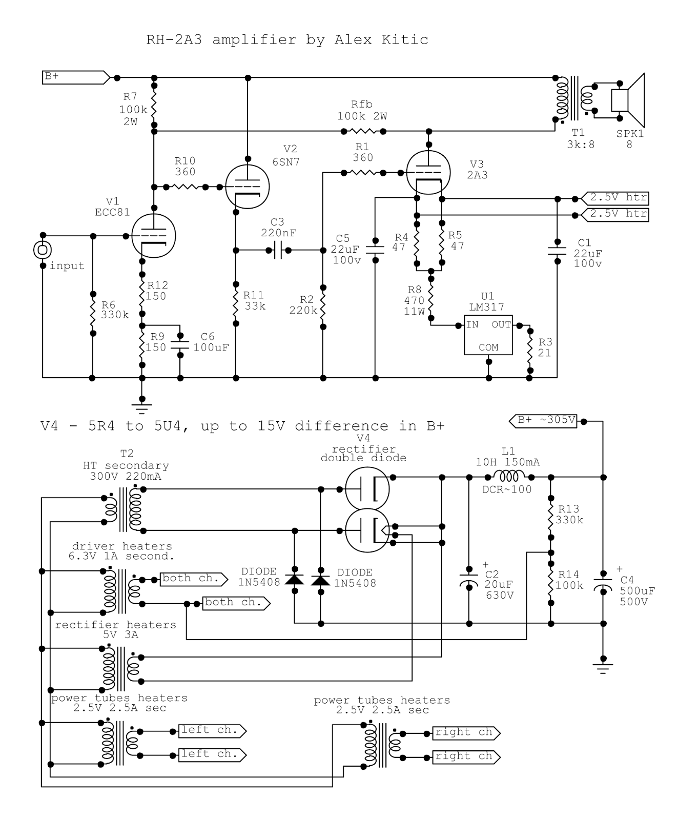
The RH300B project has spawned a schematics variation for the 2A3 tube, and from there several similar variations derive, RH2A3/1619, RH6B4G/6L6 – as presented in the previous blog entry. Indeed, the 1619 is very much compatible with the 2A3, with its 2.5V heaters, and the overall compatibility of the octal socket pin disposition as found in the special octal version of the 2A3, manufactured originally for the Audio Innovations amplifiers during the 90s. On the other hand, the 6B4G (by which I intend NOS types) and the more common Russian 6C4C (6S4S) have an identical octal pinout (5S) that is basically compatible with the 7AC pinout of the 6L6... not to mention that the 8EP pinout of the EL34 is compatible as well if we consider grounding the third grid (g3) instead of connecting it to the cathode (as a matter of fact, I prefer grounding g3 i.e. the beam former – to connecting it with the cathode, since a gradual increase of voltage on g3 leads to the forming of a kink or wave similar to that of a tetrode).

Why should we not have the best of both worlds? All we need are additional
heater secondary windings for 6.3V tubes: plural, since each direct heated tube
should have its own, and indirect heated tubes will not mind having their own
heater secondary. Now here we are facing two possibilities – either a single
6.3V 2.5A secondary where the voltage can be reduced across resistors, or
separate 6.3V 1.5A secondary and 2.5V 2.5A secondary. The latter solution is
what I have chosen, since adding resistors both clutters the interior of
amplifiers, and generates unnecessary heat by burning down voltage (not to
mention an increase in power consumption).

The Best of Both Worlds
The result is an amplifier that can use a very wide array of
tubes – from 2A3 octal and 1619, to 6A5G, 6B4G and most of the pin compatible
indirect heated tubes (even 6V6 and 6F6 can be used if the rectifier applied to
the power supply has a higher voltage drop, like the 5Y3). The basic schematics
is as published under RH6B4G/6L6 – but for a small detail: in order to avoid
the switch that selects cathode type (well, let’s get rid of at least one
switch), I have chosen to connect pin 8
(cathode in 7AC and 8EP pinouts) directly
to the “virtual cathode point” that is created on pin 6 (this pin is unused
in all the pin-outs mentioned). Incidentally, pin 8 is the mid-filament point
to which the indirect heated cathode is connected on the 6A5G.

The connection of pin8 to pin 6 is the only relevant
schematics difference between the RH6B4G/6L6 schematics, and the RH Tube Tester
Amplifier schematics… so far.
This is basically an amplifier that can use a wide array of
tubes capable of at least 15W dissipation… now that brings to mind a few other
similar tubes with different bases. The 307A that I have already designed for
(RH307A), and the 2E22 come to mind, as well as the 1624, and the evergreen 807
– all of those require the UX5 socket and an anode cap. While the compatibility
of these tubes with the amplifier could be solved with adapters – UX5 to octal
socket – they all require anode caps which would complicate the wiring of the
adapters, and the anode caps are not even the same size… Thus I have chosen to
install parallel UX5 sockets.
The UX5 Alternative
The parallel UX5 socket is wired by connecting the
appropriate pins – 1 and 5 on the UX5 are the cathode (filament) connections
and should be connected to pins 2 and 7 on the octal socket with twisted wires
(AC heating!), pin 2 of the UX5 is the screen grid (g2) and should be connected
with pin4 of the octal socket.

Now for another difference: the maximum g2 voltage of most
tubes that can be used in this amp is actually at least 300V, and thus the
1N5370B (56V 5W) zener diode in the schematics gets exchanged for a 22V zener
of the same series (1N5358B – 22V 5W), which will just allow for the voltage
drop across the primary of the output transformer, keeping the anode voltage at
a slightly higher potential than the screen grid voltage.
If you are planning to use 2E22 tubes in your RH-TTA (like I
do), you should connect pin 2 of the UX5 socket to pin 4 of the octal socket via an adequately biased zener diode
(i.e. the cathode represented by the line on the zener diode should be
connected to pin 4 on the octal socket). Of course, the zener in this case
should be the already mentioned 1N5370B – 56V5W zener – since the maximum g2
voltage for 2E22 is 250V (g2 to cathode).
The grid or pin 3 on the UX5 socket should be connected via
a grid stopper resistor (anything between 200 and 500 ohm would do) to the same
point to which the grid stopper resistor leading to the octal socket is
connected (i.e. the connection between coupling cap and grid bleeder resistor).
Connection by wire is a possibility as well, but I think that this solution will
provide better protection of the circuit from oscillations.

Last but not least, pin 4 of the UX5 socket – this pin is
either g3 in the pentodes (307A, 2E22) or NC for the 1624. Thus, depending on
whether you are planning to use the 807 or not, you may connect it directly to
pin 6 on the octal socket (virtual cathode point). If you are not planning to
use the 807 in this amplifier (like myself, since I have got no 807 tubes), you
can also connect this pin simply to ground, ensuring that g3 on 307A and 2E22
is always at 0V potential.
A perfectly safe solution for the anode connection is a 4mm
“banana” plug like the one you might use for the loudspeakers – if it is well
isolated. Make sure that the plastic isolation is good enough for at least 400V
DC if you are installing the UX5 socket and the anode “banana” jack on a metal
sheet: if you are using wood or some other isolating material (like Plexiglas)
no particular care has to be taken to isolate this jack. Having a jack instead
of a fixed wire allows the use of sets of cables with anode cap on one side
(9mm for 307A, 1624, 807; 14mm for 2E22) and a 4mm plug on the other, so they
can be removed from the amp when you are not using them, while the socket and
plug that you are not using can be covered (protected from dust and fingers).
What About UX4 Tubes?
Indeed, the 2A3 was originally meant for the UX4 socket –
and as such it was manufactured in a wide array of versions – double-plate,
bi-plate, mono-plate. The 2A3 is currently produced on UX4 socket by several
manufacturers, while the special edition octal 2A3 is probably not produced
anymore – so what if your main point of interest is the classic UX4 2A3?
The first option would be the standard RH2A3 schematics,
with UX4 sockets. Or, if you would like to use other similar tubes, like 6B4G,
6A3, or 6A5G – and you are not all that into odd direct heated pentodes and
tetrodes – you could build the RH-TTA but with an UX4 socket instead of the UX5
socket. Indeed, all those UX5 tubes are NOS only, and while prices may still be
low enough to be intriguing – you might not be interested in buying any if you
do not own some already. Having an UX4 socket in parallel with the octal socket
is still allowing for a wide range of relatively common tubes, most of which
are still being produced, or available at quite affordable prices.
Finally, you can use UX4-to-octal adapters. Besides buying the
adapters, you could build your own, just like I had to do. To build an adapter
you will need an empty octal base (preferably new, but you can also remove them
from dead or shorted octal tubes) and a suitable UX4 socket – by suitable, I
mean the round body type that can be removed from its metal retainer. Since the
base will most probably be plastic (phenolic or similar), plastic sockets might
be preferable for this use – but I chose to use ceramic sockets since I had
those available.

Adapters are rather easy to make – all you need to do is
solder short insulated pieces of wire to the UX4 socket lugs (making shure that
once you insert the socket in the octal base the lugs will not short with the
pins of the base) and remove just enough insulation from the wire pieces as to
fit the length of the octal pins: the pin will be filled with wire which should
protrude slightly on the other side, while inside the base the wire remains
insulated. Once the wires are in place, apply solder with rosin and paste,
ensuring that it flows inside the pins and makes good contact with the wire.
When you finish soldering and the check shows that no mistakes were made
connecting, and the connections are sound, you can glue the socket to the base.
While cyan-acetate glues might seem appropriate, they are rather conducive to
messy work and do not guarantee good connection unless the fit is tight. Two-component
epoxy, on the other hand, will hold perfectly regardless of material type
(ceramics on phenolic plastic or similar) and will fill the empty space if the
fit is not tight. Do not forget to cover the exposed parts with tape that you
will remove later to prevent ugly spills of glue or epoxy.
Once you make your adapters (or buy them) – you are ready to
use UX4 based tubes on the TTA! And this means some unexpected guests, like the
45…
Enter the RH45
The 45 is highly coveted as one of the best sounding tubes of
all times. A predecessor of the 2A3, it shares socket type, pinout, and heaters
voltage with that much wider known and nowadays more used DHT. It seems that,
unlike the 50 – the 45 is not yet extinct, and that holds particularly true for
SE amps applications. After all, you do not need a matched pair – similar tubes
are good enough – while with the current setting arrangements in RH amplifiers
the only thing you need to worry is finding some of these triodes in pristine
condition.

The 45 family can be basically divided as older globe types and the later ST shaped types. Interestingly enough, while many call ST shaped tubes “Coke bottles”, and find them rather sexy looking – in this case form only follows function. While the globe shape allowed for larger (and easier to manufacture) inside structures, the ST or Shoulder Tube (Type) boasts the shoulder that helps better arrange and fix the internal structure. Globe shaped tubes of the same type probably sound different than ST shaped tubes due to the different structure and possibly being more or less prone to micro-phonics.
What is the maximum anode dissipation of the 45 - or, for
that matter, the maximum anode dissipation the 2A3? This is rather difficult to
find out. While it is mostly assumed that maximum anode dissipation of 2A3
types is 15W (some datasheets actually state that value as “design center
values”, which means they may be exceeded), data on the 45 is even more
difficult to find. Guessing from several sources, the “historical” 45 had
probably 10-11W of maximum anode dissipation. Now, those were certainly not “absolute
maximum ratings”. This is not a story about constructing better than necessary
– rather about technology being not precise enough. Just like the old
skyscrapers were over-engineered and more massive than it seems necessary in
today’s terms, the clue is material tolerances. The standards for steel and
concrete were less tight than nowadays, while they had to build skyscrapers
that would not crumble with the change of wind direction, or stormy weather, or
medium intensity earthquakes – tubes were built to do their task, for instance
amplify music in a home radio receiver. 2W of output power during many hours
(years) of use meant having to use a given size or thickness for the anodes…
and so on. Whether the 45 is really a 10W anode dissipation tube, or more
powerful than that – this really depends on what you expect to get from it, and
for how long: that is the real tube power equation.

Starting from available UX4 sockets or adapters in an RH2A3
(or RH-TTA), there are several important issues for implementing the 45 (i.e. in
the RH45 amplifier):
a)
current draw should be set at 36mA – either by
adding a 15 ohm resistor in series with the current setting resistor of the
RH2A3 (TTA), or using a 36 ohm resistor in an amplifier to be used exclusively
with 45 tubes (the RH45 amplifier);
b)
lower current draw will cause a rise in the B+,
thus it is advisable to use 5R4 rectifiers with higher voltage drop (5R4GY and
5R4WGY) or 5Y3 rectifiers – another alternative that comes to mind is an 80
type rectifier (to be swapped for 5Z3 in the same UX4 socket when other higher
dissipation tubes are used drawing more current); this will ensure that the B+
stays below 340V;
c)
36mA current draw and 330-340V B+ means a bias
voltage (cathode to ground potential) of 55V approximately, which leaves about
270V across the tube, for slightly below 10W anode dissipation – so far so
good, but the LM317 will need to be replaced with a TL783 as the voltage across
the rectifier will probably exceed the maximum voltage rating of the LM317
regulator.
The TL783 is a totally transparent replacement for the
LM317: same pinout, almost identical reference voltage, same packages available
– which means that it is very easy to implement. While some think of the TL783
as an LM317 with higher voltage MOS type pass element, the differences actually
exceed the initial expectations. Nevertheless, for setting a precise current
draw at higher voltages (good for up to 125V across the regulator) the TL783 is
perfectly suited, and will add a measure of reliability to any RH amplifier,
regardless of expected bias voltage. The only issue with the TL783 is its price
(almost triple that of an LM317) and availability (not all resellers have it on
stock – but if you live outside of Serbia you will source it rather easily).
If the intended version is RH45 only, the TL783 is not
strictly necessary, since the 470 ohm resistor can be increased to about 1k
ohm, increasing the voltage drop across it and keeping the LM317 safe. But
increasing the resistor in an RH-TTA (or any of the RH2A3 versions) is not
feasible since the voltage will be either too low for current regulation, or
too high for LM317 implementation, depending on the current draw.
Last but not least, with the TL783 the DIYer does not need
to worry too much about the switch that excludes the voltage dropping resistor
from the cathode circuit – leaving it excluded for the 2A3 or 45 will not harm
the TL783 (but would kill the LM317), particularly if the heat-sink used allows
for 2-3W of dissipation. With the TL783 the main purpose of the voltage
dropping resistor remains reducing the dissipation of the regulator, keeping it
as cool as possible.
Output Power
The RH-TTA is a further development of the RH2A3 presented
earlier, thus output power and distortions are as already shown. While 2A3 and
6B4G tubes will allow about 5W output power, more can be had from the 1619 and
the other DH pentodes and DH beam tetrodes mentioned, due to the higher
efficiency of pentodes and beam tetrodes in particular. The 307A is a 15W
dissipation pentode, similar in output power to the 1619 – while the 1624 is a
1619 in ST shaped envelope with increased dissipation to 25W. The 2E22 is a 30W
dissipation pentode, but output power remains basically the same as the other
pentodes/beam tetrodes mentioned, since the output power is limited by the
voltage across the tube and the fixed current draw. The 1624 and the 2E22 can
be operated as well with GZ34/5AR4 rectifiers, increasing the available B+ for
35V approximately. The same is true of other indirect heated tubes that might
be used in the RH-TTA and have higher than 15W anode dissipation ratings, like
the EL34 or the modern 6L6 types: output power is limited by the available B+
and current, as well as the necessity to apply higher primary resistance to
keep distortions at bay. Output power will generally range between 5 and 7.5W,
which is more than enough for serious listening even on relatively inefficient
speakers (88-90dB/W/m). The RH-TTA is not about an important increase of power
using pentode and beam tetrode tubes – but about the possibility to choose in
accordance with taste and availability.

The novelty in this case is output power with the 45 tube (RH45
amplifier) – almost 3W. Whether you like the simulation results or not, listening
to the amp clearly shows that output power is slightly lower than with 2A3 tube
types, but the result is unexpectedly loud and satisfying. Basically, it is
almost the same power output possible with a classic “no feedback” 2A3 SE amp.
I have not tried to push the 45 in the same operating conditions applied to the
2A3, which would result in 15W dissipation: while I am curious enough to try it
(and see whether the anodes would develop red sports or, probably, not) – that
would be totally unnecessary and irrelevant, just like I consider pushing the
307A to 25W dissipation an unnecessary pass-time: if you need more power, there
are tubes fitting the same socket that might be used for that purpose, like the
2A3 instead of the 45, or the 2E22 instead of the 307A. The 45 is too rare to
be squandered for power at all costs. That said, 3W is almost 50% more than
your average 45 SE amplifier, without excessive stress for the tubes.

I noticed the RH300B output power being discussed on a forum
– while some were questioning the feasibility, others were quick to point out
the merits of their designs. All in all, between those who understand what it
takes, and those that do not understand, there was no mention of the particular
sound quality achieved by the various RH amplifiers. Design and engineering are
not meant to be the purpose, rather the means to achieve sonic excellence –
but those who never built one, or
listened to an RH amplifier cannot discuss the sonic merits, being confined to
accepting or negating design accomplishments. Anyway, for those interested, here is a simulation of the RH45 without Rfb at approximately 1.2% distortion...

I guess this example is illustrative enough - while correct application of feedback is paramount in RH amplifiers, some merit should be given to distortion cancellation as well.
I guess this example is illustrative enough - while correct application of feedback is paramount in RH amplifiers, some merit should be given to distortion cancellation as well.
Output Transformers
Just like I suggested when writing about the RH2A3/1619, for
the operation of the RH-TTA with a wide array of tubes you will need a flexible
transformer. While you could get away with a usual 3k primary with 8 or 4 ohms
secondary – if you use the 4 ohms secondary with your 8 ohm speakers you will
get approximately 6k primary loading – such arrangement is valid only if you do
not change your speakers. Assuming 4 ohm speakers, the 8 ohm output will become
approximately 1.5k – which is not a value usable with the RH-TTA: if that is
the case you would obviously need to change your output transformers as well.

The Lundahl LL1623 is extremely flexible, and besides the
possibility to configure from 1.6k to 5.6k primary and a choice of 4, 8, and 16
ohm secondary configurations – you can easily arrange the “neighboring” values
to be changed with switches, like I did. Operating 3 switches simultaneously
(it is difficult to find a two way 12 contact switch, or a rotary switch that
has adequate current capability) I can choose between 3k and 5.6k primary
loading into 8 ohms (on both channels at the same time), and if in the future I
change speakers (for instance, 4 ohm units) I would just have to reconfigure
the wiring harness. I regard this characteristic as paramount, particularly in
a DIY project – since transformers are virtually “forever”: they do not change
their characteristics appreciably with time, and when built with modern
isolation materials they should have a much extended lifespan. Therefore, if
nothing else, you should be able to reuse your transformers in some new project
one day, and that is where flexibility means good investment.

If the RH-TTA is to be realized as a more limited solution –
like just using 2A3, 6A3, 6B4G, and 6A5G, for instance… any good 3k primary
output transformer would do, including the one I mentioned already. If the
choice is to use only the UX5 pentodes and beam tetrodes, any good 5k-6k
primary output transformer would do, again – including the one I mentioned.
The RH45 (standalone version) would require a 5k-6k output
transformer. Since the output power is rather limited at almost 3W, it could
even be built with output transformers salvaged from EL84 consoles, the type of
output transformers that DIYers often use to build RH84 amplifiers with
success. But I guess that most would opt for higher quality alternatives, since
the 45 is a highly coveted and rather rare tube.
Amplifiers, Tubes, Lifetime, and Boredom
On the other hand, expensive boutique tubes and rare NOS
tubes are not something I would recommend. Good examples for this might be the
(original) NOS WE 300B tubes, including the later manufactured WE300B tubes (no
comments necessary here I believe) or the EML tubes. While the various Emission
Labs tubes might be of exceptional manufacturing quality, viewed from a
historical perspective I cannot see a rational reason to use such tubes at
exorbitantly high prices (take a look at the price list and ask yourself are
you buying historical rarities or tubes made yesterday “to exacting standards”:
the prices are ridiculous since you probably cannot use them as a means to
avoid taxation, unlike investments in real estate). To rephrase the previous
tought, while they might last a long time, they will not last forever, and only
time can tell whether they will last as long as the “original” WE300B tubes
were reported to last in the theater amplifiers (decades, or tens of thousands
of working hours). Even if they do last 20 years of everyday operation, I guess
one might get tired of listening to the same amp and the same tubes for 20
years? (while WE was probably happy for not having to replace the tubes in the
amps they rented and which represented a source of income and business
venture). Well, life is not a permanent condition, too – while you might reuse
your transformers in a new amp one day, with different output tubes, what good
is a tube that might last 20 years and it costs more than several complements
of tubes for several amplifiers that you might use in those 20 years? Besides
that, high precision and attention to detail is today represented as a path to
great sound, while just throwing a glance on the interior of some of the tubes
renowned as great sounding (45s, particularly the globe versions) should make
you wonder how is it possible to show such low attention to detail (was it,
really) and still get lasting quality and great sound? Last but not least, even
if a tube is capable of exceptional sound quality, it will not provide said
sound quality without a good output transformer, good passive components, maybe
good drivers… not to mention good schematics exploiting the quality of the
components: a tube is just a component that we use for a given period of time
in our lives.

I am aware that manufacturing tubes in small volume
nowadays, and eventually starting from scratch, is not cheap or investment
efficient, I frequently ask myself how is it possible for the Chinese factories
to produce acceptable replicas of “extinct” tubes? While those tubes can hardly
be considered exact replicas, they indeed tend to work just fine in their own
right. I am not questioning the quality difference between boutique and Chinese
production, although it is often perceived as higher than it actually is, but
addressing the quality vs. price ratio, as an obvious function of the perceived
value. Sometimes marketing is used to mix true and useful information with
not-so-true statements backed by assumptions…

Anyway, this type of “boredom” with common places in life and all the repetitive experiences of our everyday routine
(and the same tubes for 20 years) is something that I am addressing with the RH-TTA:
you may as well build several amps, but finding place for them on your shelves
might be a problem - or you might not have the time to build new amps as often as you might want to. A flexible amplifier will let you use and explore many
tubes, changing nuances and enjoying your music without too much effort: not
even having to remove cables to connect another output, or another amplifier.
While the RH Universal was directed at those requiring power and simplicity,
the RH-TTA is directed at those who are interested in exploring the
possibilities while output power is an issue relegated to the background.
The Tube Tester Amplifier
This amplifier is capable of using indirect heated tubes
without modification, but most tubes I have used or tried it with are direct
heated types. At first I was thinking about “DH-Universal”, but the presence of
a number of switches that modify the characteristics to the tube, and the
paralleled sockets are reminiscent of a tube tester.

First of all, there are 3 switches necessary to choose between
3k and 5.6k primary resistance – those should not be operated while the
amplifier is operating, of course, just like all the other switches: all those
choices are not something that is made “on the run”, but a choice between
conditions required to operate. Located between the output tubes are two
additional switches: one is used to exclude the voltage dropping resistor from
the cathode circuit (necessary when operating the pentodes and beam tetrodes,
since their bias voltage is less than 20V and the resistor would preclude
correct operation of the current draw regulator), having a “triode” and
“pentode” setting. The other switch is used to choose current draw, 60mA or
36mA (for the 45), which is achieved by bypassing the additional 15 ohm
resistor.
Using the switch to bypass a resistor means that if the
switch loses contact, the worst case scenario is the most benign – tubes will
be operated at 36mA, and the voltage dropping resistor will remain in the
cathode circuit at all times. The operation of the amplifier will be
compromised in terms of performance for the duration of the fault, but neither
the tubes nor other components will be at risk.
On either side of the rectifier tube, near the cathode
connections of the output tubes, two larger switches (25A contacts) are used to
choose between 2.5V or 6.3V secondary. This obviously allows to use i.e. 2A3 or
6B4G tubes. The unused secondary is left “open”, thus no current is drawn and
no additional heat dissipated. Indeed, trying to operate 2A3 tubes on 6.3V might
damage them… but I guess the DIYer is going to be aware of that – on the other
hand, 6B4G tubes will not light their filaments at 2.5V and there should be no
sound output or current draw since the cathodes will not be able to emit
electrons: this condition might damage the tubes as well, contrary to what many
believe.
The last switch is located out of sight on the back side
near the power transformer, since it is rather rarely used. The purpose of this
switch is to allow 5.5V heaters operation with the correct voltage – it is an 8
contacts 25A switch which is basically bypassed from side to side with 0.39 ohm
resistors. When the switch is closed, the resistors are excluded and 6.3V are
directed to the heaters voltage switch. When the switch is open, the current
flows through the resistors: at 1A current draw each resistor drops 0.39V, thus
5.52V are delivered to the heaters voltage switch, to be used for the 307A.

If built with UX4 sockets instead of UX5, or if UX4 to octal
adapters are used, the 300B tube can be used as well – the 8 contacts switch
has to be fitted with different resistor values (0.56 ohm) to provide 5V to the
300B heaters. It is questionable whether it makes sense to use the 300B tube in
the RH-TTA, since the output power is going to be limited by the available
voltage and current draw, in a similar way in which other more powerful tubes
are limited. The 300B will yield just 5.5W at 1% distortion – but the DIYer who
would build the RH-TTA is probably satisfied to get 5W from the 2A3 and might
be interested in getting approximately the same power from 300B tubes – without
building another amplifier.

While the 300B can actually yield a lot more output power, operating it at low anode dissipation will without doubt guarantee long tube life and trouble-free operation. Those for whom 5W might be enough would probably enjoy the 300B and its characteristic sound in this circuit…
While the 300B can actually yield a lot more output power, operating it at low anode dissipation will without doubt guarantee long tube life and trouble-free operation. Those for whom 5W might be enough would probably enjoy the 300B and its characteristic sound in this circuit…
Last But Not Least – The Sound
All this text, and no mention of how does the amplifier perform in the music reproduction scope…
basically, the sound quality issue was covered in my post on the RH2A3/1619
amplifier, thus the points worth mentioning are both comparison between the
sound of various tubes, and the implication of having a finalized well laid-out
box against a breadboard amplifier.
The RH-TTA ended up being quite large by my standards – it
almost dwarfs the RH300B. I was unable to fit all the necessary parts in the
rather small box in which I have fitted the RH300B, but I used the extra place
to ensure that there is no interaction between the various elements.

All transformers are hidden inside the box, and the toroid transformers are vertically mounted, further minimizing the effect of their field on the amplifier. With 2.5V output tube types no noise or hum is audible even with an ear on the woofer or midrange of my 88dB/W/m speakers – although the heating is AC. Enough said: no need for DC on the heaters in this amplifier, and that is probably one of the reasons it sounds as good as it does – but this is a different topic, one that may require further research and discussion.

All transformers are hidden inside the box, and the toroid transformers are vertically mounted, further minimizing the effect of their field on the amplifier. With 2.5V output tube types no noise or hum is audible even with an ear on the woofer or midrange of my 88dB/W/m speakers – although the heating is AC. Enough said: no need for DC on the heaters in this amplifier, and that is probably one of the reasons it sounds as good as it does – but this is a different topic, one that may require further research and discussion.
The sound has improved in comparison to the previous
impression – maybe the output transformers have gone through some break-in
period, and probably the remaining components have also benefited from a
break-in period. I am not a big fan of the breaking-in theory: either it works
or it does not… but it is a matter of fact that improvements in time can be
heard. Good quality stuff usually sounds good from the first note, although it might improve with the passage of time. The basic tone quality of the amplifier remains unchanged regardless of
output tube used, but each tube brings its intrinsic sound quality to the mix,
like a distinct flavor.
The overall winner in the triode class is the NOS 6B4G (double-plate,
black anodes), showing a margin of midrange quality above the Shuguang special
octal 2A3 (bi-plate, black anodes) version: the new generation of mono-plate
current production 2A3 tubes probably sound slightly better and can be directly
compared to the NOS 6B4G. By the way, I was using this same pair of 6B4G tubes
for years in a classic no feedback SE design, and they have probably worked at
least 2000 hours – but they still look and test like new… and their price when
manufactured was nowhere near the asking price of the current production
boutique tubes. As a rule of thumb, the 2A3 family tubes are slightly forward
in the midrange, but the midrange nevertheless shows warmth of tone.
The 1619 is my favorite in the direct heated
pentodes/beam-tetrodes class. While being a rather ugly metal tube (no heaters
to warm up your sight), it has no cap and the envelope is grounded, thus very
safe. The sound is very liquid, with an overall quality that goes a long way
towards beating the particular qualities of the 307A or the warmth of the 2E22.
I have not tried the 1624 in this circuit since I haven’t got any – and it
would be interesting to assess whether it is better or worse than it’s lower
power metal sibling. As a rule of thumb, the pentodes tend to leave the
impression of better extension and smoother frequency response, without
midrange forwardness – but without the midrange warmth shown by the DHTs. This
is more than anything else a matter of taste – the choice between rich overall
tone, or pronounced yet warm midrange (more or less).
Finally, the highly coveted 45: I am not mentioning it in
the triode class since it is operated at lower current and has lower power
dissipation. The 45 tube is in a class of its own. My expectations were indeed
very high, and while this is not “sound like I have never heard before”, the 45
does, even in the newer ST shape (the only 45s I have are Sylvania ST shape,
provided by a DIY friend) confirm the intrinsic qualities that it was coveted
for.

The particular sound of the 45 is rather different than the
6B4G some consider as its descendant (in particular, the bi-plate version is often considered as two 45s in a single tube). The 45 shows none of the mellowness
expected from DHTs – on the contrary, it is lightning fast and detailed. While
bass is well defined, fast and quite strong (unexpectedly so), the mids and
highs are extremely detailed, liquid, and fast at the same time. The closest
approximation to this type of sound is actually the “fake mesh” globe shape
300B of current production. Just like this particular 300B might seem bass shy,
the 45 seems to lack some bass volume – at least until the listener understands
that it is more about a lack of oomph, while the vibrations are very much present.
But the particular quality of the mids and highs is what fascinates the
listener – making it difficult to change the 45 for another tube, just like
many prefer the sound of the “fake mesh” 300B to other more solid types, due to
the transparency and liquidity of mids and highs. The less pronounced bass, the
power limitation (on rather inefficient speakers in a rather large room) – it
all fades away against the quality of the mids and highs. There is neither the
particular richness of tone like with the pentodes, nor the forward but warm
midrange characteristic of the DHTs: the strength of the 45 seems to be the
speed, and liquidity, combined with a forgiving distortion pattern reminiscent
of dust showing in rays of sunshine. On the other hand, the 3W provided by the
45 in this amplifier can go quite loud, and the soundstage thrown is very large
and airy.
Credits
Just like on previous occasions, I would like to thank all
those who support my work – in particular Mr. Per Lundahl, and a group of
DIY-ers based in England who post on the audio-talk forum. New designs and
developments would remain just ideas and afterthoughts without the help of
friends from all over the world who follow my work and my blog.